
Page 47 - MetalForming March 2019
P. 47
The Science of Forming
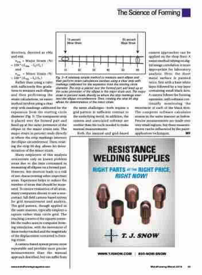
10-percent 60-percent Minor Strain Major Strain
10 20 30 40 50 60
direction, denoted as eMa and emi:
eMa = Major Strain (%) =100*((LMa –Li)/Li)
and
emi = Minor Strain (%) =100*((LMi –Li)/Li)
Fig. 3—A relatively simple method to measure each ellipse and then perform strain calculations involves using a clear strip with markings calibrated for the expansion from the starting circle diameter. The strip is placed over the formed part and lined up at the outer perimeter of the ellipse in the major strain axis. The major strain in percent reads directly as where the strip markings inter- sect the ellipse circumference. Then, rotating the strip 90 deg. allows for determination of the minor strain.
camera approaches can be applied on the shop floor. A newer method relying on dig- ital image correlation is more appropriate for laboratory analysis. Here, the sheet metal surface is painted twice, first with a base white layer followed by a top layer containing small black dots. A camera follows the forming operation, with software con- tinually monitoring the
Rather than using a ruler
with sufficiently fine grada-
tions to measure each ellipse
and then performing the
strain calculations, an easier
method involves using a clear
strip with markings calibrated for the expansion from the starting circle diameter (Fig. 3). The transparent strip is placed over the formed part and lined up at the outer perimeter of the ellipse in the major strain axis. The major strain in percent reads directly as where the strip markings intersect the ellipse circumference. Then, rotat- ing the strip 90 deg. allows for deter- mination of the minor strain.
the same challenges—both require a grid pattern in sufficient contrast to the underlying metal. In addition, the camera and associated software are costlier than the tools needed to make manual measurements.
Both the manual and grid-based
movement of each of the black dots. The computer software calculates strains in the same manner as before. Precise measurements are made over very small regions, but these measure- ments can be influenced by the paint- application techniques. MF
RESIS
ST
T
T
T
A
A
A
Many employers of this analysis concentrate only on known problem areas due to the time consumed in measuring all ellipses on a formed part. However, this shortcut leads to a risk of not characterizing other important areas. Experience helps to reduce the number of areas that should be meas- ured. To ensure evaluation of all areas, many companies choose to use a non- contact, full-field camera-based system for grid measurement and analysis. The grid pattern, though applied in the same manner, typically employs a square rather than circle grid. The touching corners of the squares resem- ble the nodes seen in computer form- ing simulation, with the movement of these nodes tracked and the magnitude of the displacement converted to form- ing strain.
A camera-based system proves more repeatable and provides more precise measurements than the manual approach described, but can suffer from
NCE
G SUPPLIE
AN
E
W LDIN
G
S
S
RIGHT P
ARTS A
RIGHT NOW!
A
T THE RIGHT PRICE,
T
www.metalformingmagazine.com
MetalForming/March 2019 45
WWW.TJSNOW.COM | 800-NOW-SNOW
