
Page 46 - MetalForming March 2019
P. 46
The Science of Forming By Daniel J. Schaeffler, Ph.D.
Introduction to Strain Analysis: Measuring Strains
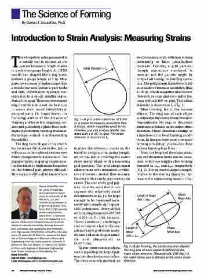
Initial Diameter = Li
The elongation value measured in a tensile test is defined as the percent increase in length relative to a reference gauge length. An ASTM tensile bar, shaped like a dog bone, features a gauge length of 2 in. Most parts have a more complex shape than a tensile bar and, before a part necks and fails, deformation typically con- centrates in a much smaller region than a 2-in. span. These are two reasons why a tensile test is not the best tool to assess sheet metal formability of stamped parts. Dr. Stuart Keeler, the founding author of the Science of Forming articles in this magazine, cre- ated and publicized a plant-floor tech- nique to determine forming strains on stampings—critical to understanding formability.
The dog-bone shape of the tensile bar increases the chances that failure will occur in the reduced section over which elongation is determined. For stamped parts, mapping locations on the flat blank to high strain locations on the formed part proves difficult. This makes it difficult to know where
Danny Schaeffler, with 30 years of materials and applications experi- ence, is co-founder of 4M Partners, LLC and founder and president of Engineering Quality Solu- tions (EQS). EQS provides product-applications assistance to materials and manufacturing com-
panies; 4M teaches fundamentals and practical details of material properties, forming technolo- gies, processes and troubleshooting needed to form high-quality components. Schaeffler, who also spent 10 years at LTV Steel Co., received his Bach- elor of Science degree in Materials Science and Engineering from the Johns Hopkins University in Baltimore, MD, and Master of Science and Doctor of Philosophy degrees in Materials Engineering from Drexel University in Philadelphia, PA.
Danny Schaeffler
248/66-STEEL • www.EQSgroup.com
E-mail ds@eqsgroup.com or Danny@learning4m.com
Fig. 1—A grid pattern diameter of 0.200 in. is easier to measure accurately than 0.100 in., which magnifies small errors. However, you can analyze smaller fea- tures with a 0.100-in. grid. This initial diameter is denoted as Li.
to place the reference marks on the blank to designate the gauge length, which has led to covering the entire sheet metal blank with a repeating grid pattern. The grid shape must allow strains to be measured in what- ever direction metal flow occurs. Starting with a circle grid makes this easier. The size of the grid pat-
electrochemical etch, with laser etching increasing as laser installations increase. Painting a grid pattern, though sometimes employed, is messier and the pattern might be scraped off during the forming opera- tion. The grid pattern diameter of 0.200 in. is easier to measure accurately than 0.100 in., which magnifies small errors. However, you can analyze smaller fea- tures with a 0.100-in. grid. This initial diameter is denoted as Li (Fig. 1).
After forming, the circles become ellipses. The long axis of each ellipse is defined as the major strain direction. Perpendicular (90 deg.) to the major strain axis is defined as the minor strain direction. These directions change as a function of the local forming condi- tions. In images from your computer forming simulation, you will see these as your forming flow lines.
Next, the length of the major strain axis and the minor strain axis are meas- ured, with these lengths after forming denoted as LMa and Lmi, respectively (Fig. 2). The percent change in length, relative to the starting diameter, rep- resents the engineering strain in that
Length of Major Axis = LMa
Length of Minor Axis = Lmi
Ellipse Major Axis
Ellipse Minor Axis
44 MetalForming/March 2019
www.metalformingmagazine.com
tern must be such that it can capture the relatively small deformation zone, yet be large enough to be measured accu- rately with simple and repeat- able techniques. Using circles with starting diameters of 0.100 or 0.200 in. fit this balance. These combined challenges and constraints led to the cre- ation of circle grid strain analy- sis, also called circle grid analy- sis and abbreviated as CGSA/CGA.
To start your strain analysis, etch a repeating circle grid pat- tern into the sheet metal surface. The most common method: an
Fig. 2—After forming, the circles become ellipses. The long axis of each ellipse is defined as the major strain direction. Perpendicular (90 deg.) to the major strain axis is defined as the minor strain direction.
