
Page 16 - MetalForming March 2019
P. 16
Tooling by Design
By Peter Ulintz
Stamping Nonferrous Alloys
Nonferrous metal alloys have been used since the beginning of civilization. The discovery of copper around 4500 BC marked the end of the Stone Age and the beginning of the Copper Age. One thousand years later, humans discovered that copper could be combined with tin through smelting, which began the Bronze Age.
Recently, much has been published about forming and stamping high- strength aluminum alloys, with research fueled by global automotive manufacturers and their desire to reduce vehicle mass and improve fuel economy by replacing steel compo- nents with aluminum.
Aluminum Challenges
Aluminum is one-third the weight of comparable steel stampings of the same thickness, making it an attractive alternative for mass-reduction efforts. Unfortunately, many automotive grades will form much like 100,000-psi yield strength steel and only have about two- thirds of the stretching ability. Due to planar anisotropy and forming limits, stamping aluminum successfully depends on part design, the shapes of the blanks, drawing depths, reduction ratios, wall angles and product-feature
Peter Ulintz has worked in the metal stamping and tool and die industry since 1978. His back- ground includes tool and die making, tool engi- neering, process design, engineering manage- ment and advanced product development. As an educator and technical
presenter, Peter speaks at PMA national seminars, regional roundtables, international conferences, and college and university programs. He also pro- vides onsite training and consultations to the met- alforming industry.
Peter Ulintz
Technical Director, PMA pulintz@pma.org
transitions. All interact to affect the cost and quality of an aluminum stamping. Deep-drawing aluminum can be challenging when stampers have little experience with the various alloys. Depending on alloy and temper, some grades can have limiting draw ratios similar to that of steel, while others are substantially less. Consider keeping the limiting draw ratio (LDR) below 1.6 unless you have previous experi- ence with the particular alloy. An LDR of 1.6 is equivalent to an approximate 38-percent reduction for the first draw. Subsequent redrawing percentages should be approximately 22, 17 and 12 percent, assuming that the ratio of material thickness to blank diameter
is greater than 0.25.
Many die design handbooks contain
draw-reduction tables. These reduction tables were developed decades ago pri- marily for low-carbon steel. Due to dif- ferences in work hardening behavior, surface topography and other factors, these tables should not be used for aluminum, copper, nickel or any other nonferrous alloy.
Copper Alloys:
Process Considerations
Many copper, brass, beryllium cop-
per and nickel alloys used to produce small clips, electronic components and medical devices are produced from cold-rolled coil strip, automatically fed into progressive dies and high-speed stamping operations. The coil strip may be supplied in the annealed (dead soft) condition or a temper condition by cold working the strip prior to coiling,
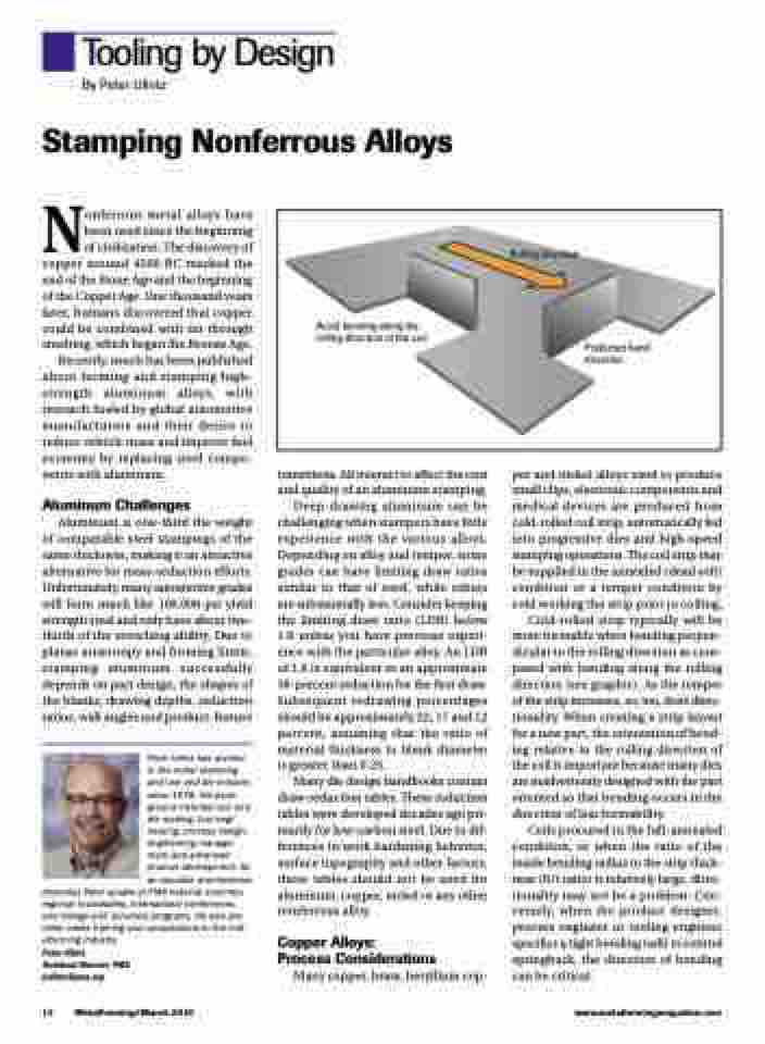
Cold-rolled strip typically will be more formable when bending perpen- dicular to the rolling direction as com- pared with bending along the rolling direction (see graphic). As the temper of the strip increases, so, too, does direc- tionality. When creating a strip layout for a new part, the orientation of bend- ing relative to the rolling direction of the coil is important because many dies are inadvertently designed with the part oriented so that bending occurs in the direction of less formability.
Coils procured in the full-annealed condition, or when the ratio of the inside bending radius to the strip thick- ness (R/t ratio) is relatively large, direc- tionality may not be a problem. Con- versely, when the product designer, process engineer or tooling engineer specifics a tight bending radii to control springback, the direction of bending can be critical.
Rolling direction
Avoid bending along the rolling direction of the coil
Preferred bend direction
14 MetalForming/March 2019
www.metalformingmagazine.com
