
Page 17 - MetalForming December 2017
P. 17
continuously through the bottom of the stroke, energy per stroke is 3000 in.-tons. Plotting this profile on the curve shows that the area under the curve equals the energy. If the force increases to 1500 tons within the last 0.25 in. of stroke, the energy required will increase. Using the same area-calculation approach, determine the total required energy by summing up all of the area under the curve.
Offset-Loading Considerations
The amount of offset loading applied in the dies represents another die-loading parameter to address. This typically becomes a bigger issue in transfer- or progressive-die appli- cations. The die is more centrally located for single-die applications and tends to apply a balanced load in the press. But die loads can be higher at the entrance end than that at
loading to help bring the offset back to a more uniform load. Running a mechanical press with a high offset tends to increase slide-gib wear and cause other bearing-wear issues.
Using a 2000-ton press as an example, the 60/40 percent rule can control the offset load. If the entrance side of the press runs at full tonnage of 1000 tons, then the right side should be loaded with at least 670 tons. This loading shows a total die load of 1670 tons, as the entrance side loads at 60 percent of this amount, and the exit end loads at 40 percent.
Take the Challenge
Maintaining limitations for die loading is worth the effort. Develop a log of die tonnage, corresponding-position in.- stroke, and energy per stroke. Tonnage-monitoring devices help to document tonnage and provide understanding of the corresponding-position in.-stroke.
Always demand that the tonnage and energy specifica- tions for new equipment be provided, and be sure that they are clearly documented and explained. Used equipment may require more investigation to obtain these critical specifications.
Bottom line: Taking the time to obtain press specifications and evaluate actual die loading matters. It’s a challenge worth taking. After all, the life of your mechanical press
depends on it.
MF
RAMPIN
G
G
P RODUCTION?
UP
PR
R
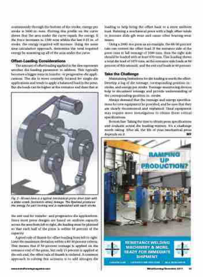
Fig. 2—Shown here is a typical mechanical-press drive train with a slider-crank (eccentric-drive) linkage. The flywheel produces the energy for part forming and is replenished with each stroke.
the exit end for transfer- and progressive-die applications. Since most press designs are based on uniform capacity across the area from left to right, die loading must be planned so that each half of the press is within 50 percent of the capacity.
A good rule of thumb for offset loading from left to right: Limit the maximum deviation within a 60/40 percent criteria. This means that if 50-percent tonnage is applied on the entrance end of the press, but only 15 percent is applied at the exit end, the offset rule of thumb is violated. A common approach to solving this scenario is to add nitrogen die
RESIST
ANCE WELDING
A
MA
READ
.COM | USEDSPO
Y & MORE,
Y FOR IMMEDIAT
CHINERY
TE
. WELDER.COM | (80
SHIPMENT
.
www.metalformingmagazine.com
MetalForming/December 2017
15
T
-SNO
JSNO
W
T
0) NO
W
J
W
