
Page 16 - MetalForming December 2017
P. 16
Mechanical Presses
...begins with understanding die-loading limitations
BY ANTHONY RANTE
15
10
5
0
0 500
1000 1500 2000 Tonnage (U.S. tons)
Your understanding of press design and how it limits die loads could be life-changing...for your mechanical press. The following design parameters for single, transfer, or progressive-die applications must be addressed as you plan dies for your press.
Tonnage Curve
Each mechanical press should include a tonnage curve within the documentation set. The curve, a plot of press position vs. tonnage, is important for die planning. The rated position of the press, typically about 0.5 in. from bot- tom, means that the full tonnage of the press can be applied in the dies between the rated position and the bottom of the stroke. The press designer will determine the main gear torque at the rated position, and then hold that value as a limitation at all points above the rated position. Since the press linkage loses mechanical advantage above the rated position, the resulting allowable tonnage decreases. The reduction in tonnage above this point is less significant for link-drive presses, as the mechanical advantage drops off at a less dramatic rate.
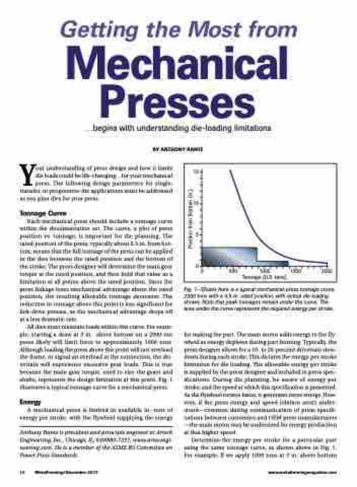
All dies must maintain loads within this curve. For exam- ple, starting a draw at 3 in. above bottom on a 2000-ton press likely will limit force to approximately 1000 tons. Although loading the press above this point will not overload the frame, or signal an overload at the connection, the dri- vetrain will experience excessive gear loads. This is true because the main gear torque, used to size the gears and shafts, represents the design limitation at this point. Fig. 1 illustrates a typical tonnage curve for a mechanical press.
Energy
A mechanical press is limited in available in.-tons of energy per stroke, with the flywheel supplying the energy
Anthony Rante is president and principle engineer at Artech Engineering, Inc., Chicago, IL; 630/880-7297, www.artecengi- neering.com. He is a member of the ASME B5 Committee on Power Press Standards.
Fig. 1—Shown here is a typical mechanical-press tonnage curve, 2000 tons with a 0.5-in. rated position, with actual die loading shown. Note that peak tonnages remain under the curve. The area under the curve represents the required energy per stroke.
for making the part. The main motor adds energy to the fly- wheel as energy depletes during part forming. Typically, the press designer allows for a 10- to 20-percent drivetrain slow- down during each stroke. This dictates the energy-per-stroke limitation for die loading. The allowable energy per stroke is supplied by the press designer and included in press spec- ifications. During die planning, be aware of energy per stroke, and the speed at which this specification is presented. As the flywheel rotates faster, it generates more energy. How- ever, if the press energy and speed relation aren’t under- stood—common during communication of press specifi- cations between customers and OEM press manufacturers —the main motor may be undersized for energy production at that higher speed.
Determine the energy per stroke for a particular part using the same tonnage curve, as shown above in Fig. 1. For example: If we apply 1000 tons at 3 in. above bottom
14 MetalForming/December 2017
www.metalformingmagazine.com
Position from Bottom (in.)
