


 Stuart Keeler
Some Forming Problems Have No Solutions
October 1, 2016Comments
Metalforming-industry representatives from around the world gathered a few months ago to discuss solutions to several challenges facing manufacturers. The first problem discussed: fracture modeling. The complaint read: The forming-limit curve (FLC) is no good because it cannot predict the onset of cracking during blanked-edge stretching.
Failure occurs well below the value predicted by the FLC. The solution we discussed centered on the fact that the FLC depends on the n-value. The n-value of the workpiece material cannot be used, as it does not represent the n-value of the material after forming, shearing and other deformation. Much of the deformation and damage often goes back half the sheetmetal thickness from the cut edge.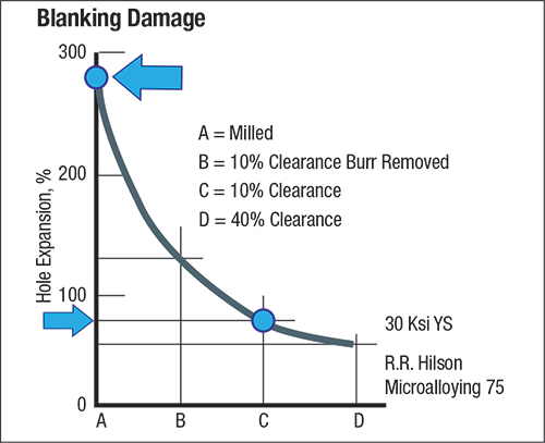
Fig. 1—Typical hole expansion is 80 percent. A milled hole will provide 280-percent expansion.
Fig. 1 shows the dependency of edge stretch on clearance and burr removal prior to a hole-expansion test. For this sample, the 10-percent clearance allowed a hole expansion of 80 percent. When the hole was milled, the hole expanded by 280 percent. One can imagine the cracks, rough edges, workhardening and other damage during cutting and all other processing of the edge. This makes the prediction of fracture severity and hole expansion very difficult and usually impossible.
The second problem discussed: friction modeling. Friction is everywhere—some good, some bad. From 1994 to 1999, virtual forming made significant advances in helping designers create successful part and die designs. However, one problem consistently created roadblocks: A single coefficient of friction (CoF) does not suffice for all of the different friction values that occur between the parts and the die. Some of the problems encountered while trying to create a friction map:
Basic deformation mode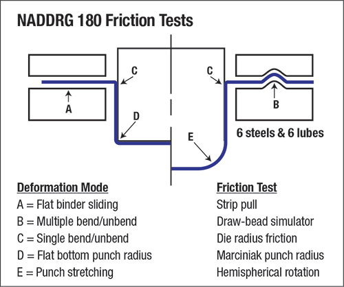
Fig. 2—A lubricant that works well for the upper three tests (A, B, C) will be a poor lubricant for the bottom two tests (D, E) and vice-versa. - Micro-geometry of the sheetmetal
- Micro-geometry of the tool steel
- Lubricant type, thickness and breakdown
- Speed of surface movement
- Interface pressure and temperature
- Prior history of deformation.
A major research team was established with experts from the automotive, steel, aluminum and metal-stamping industries. Several universities were hired as contractors. LSDyna did the computer analyses. While some minor bits of information were gained, after 5 yr., the final friction answer was, “Cannot track CoF.” There are so many constantly changing CoF combinations that the numbers have no meaning.
Members of the North American Deep Drawing Research Group conducted a series of friction tests (Fig. 2) on six steel grades using six different lubricants and five different friction modes. The tests indicated only one trend: A lubricant that worked well with tests A, B and C did not work well with tests D and E, and vice-versa. The data indicated that the A, B and C friction tests constantly received new material. Fresh sheetmetal and lubricant were fed into the deformation zones and then continuously replaced by more fresh material and lubricant. Friction conditions for D and E were just the opposite. The starting material and lubricant enter the low areas and are not replaced. MF
View Glossary of Metalforming Terms
Technologies: Quality Control
Comments
Must be logged in to post a comment. Sign in or Create an Account
There are no comments posted. Quality Control
Ascential Technologies Appoints Divisional CEO to Specialty ...
Wednesday, April 24, 2024
Brinell, Rockwell and Vickers Hardness Testing: Use and Misu...
Daniel Schaeffler Friday, April 1, 2022
 Quality Control
Troubleshooting Sheet Metal Forming Problems, Part 2: The St...
Daniel Schaeffler Friday, February 26, 2021
 Quality Control
Cobot Setup Offers Pick-and-Place for Material and Product S...
Wednesday, April 29, 2020
 Video
Video