Case Study 2
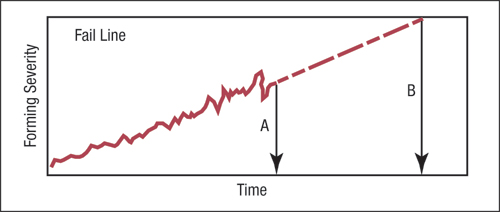 Forming this stamping causes a measurable rate of wear on the die that increases forming severity. The stamping is produced continuously in a dedicated press. The initial curve of increasing forming severity was measured between the start of the refurbished die and the onset of failure (B). A UTG and probe locater templates are used to construct the initial curve. Subsequent UTG measurements track whether wear rate is similar to the initial curve. If the rate is higher or lower than expected, an immediate investigation is initiated.
Question: Should the die be refurbished at point A or B? Pulling the die at point A not only is safer, but refurbishing time could be significantly shorter. Running the stamping until point B can cause extreme damage to the die or press.
Remember that the fail line represents the very onset of a local neck that may not be observed until the number of additional stampings become very severe and fracture.
Case Study 3
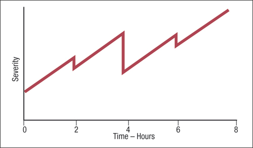 This pattern of increasing forming severity results from a temperature increase in the stamping. Note the small drop in temperature at morning and afternoon breaks, and a larger drop at lunch time.
As with previous case studies, forming severity was determined by UTG measurements of thickness at the highest severity location and at a zero-deformation location. During this study, temperature was measured with a laser thermo-gun at UTG-measurement locations on the stamping and the die. The gradual increase in severity during the day shift was due to the temperature increase of the ambient air in the press shop. A different study showed that an increase from 70 F to 84 F was sufficient to cause stamping severity to change from the bottom of the yellow zone (safety margin) to inside the red zone (failure). This increased operating temperature can lead to a reduction in lubricant viscosity, and even lubricant breakdown. Die dimensions and shape also are temperature-dependent.
Case Study 4
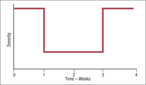 Forming severity climbed to a high level with this difficult stamping, requiring the press operator to make constant adjustments to the press, die or blank.
On Monday morning of the second week of running SDC evaluations, forming severity was low and stayed low for two weeks. On the Monday morning of the third week, forming severity returned to the high level.
Checking with the personnel office, we find that the normal press operator was on vacation during the low-severity period. The replacement operator, who confesses to being inexperienced with this particular stamping, says that he simply looked up the original die-buyoff settings, made the changes and then left the operation alone.
A number of plants will reset press and dies back to their initial settings (buyoff or die run) before making any other changes to the forming system.
Case Study 5
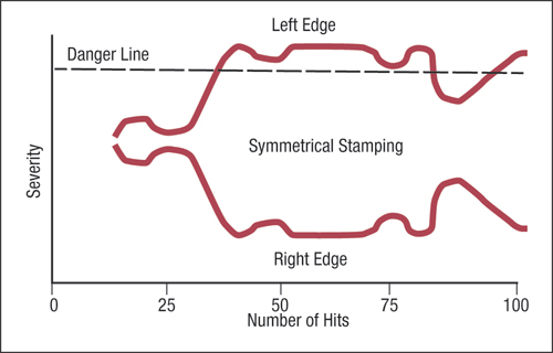 After approximately 40 hits on a new die, the left edge of a symmetrical stamping began necking and randomly breaking. Severity data from UTG measurements were acquired at least every five hits from the right and left sides of the stamping. Examining the forming-severity plot reveals three interesting features.
First, the die initially created nearly equal right/left severity levels that were well a from the danger line. Second, after 25 hits the severity of the right and left side began to dramatically diverge—the right edge experiencing reduced severity and the left edge increasing in severity. Third, the severity deviations are equal in magnitude and in sync, but completely opposite in direction. This forming pattern suggests the blank guides are being intentionally or accidently relocated. Examination showed the guides did not center the blank over the die. Everybody wanted to center the guides, but the severity data were telling a more important story.
The right side of the stamping was being produced correctly, with a very low forming severity. The left guide then was reset to the same relative location as the right guide. Obviously, the blank width had to be made narrower.
Solving this problem not only lowered the forming severity of the entire stamping, but also reduced the blank size and the cost of the stamping. MF
On August 21 and 22 in Detroit, MI, Stuart Keeler and Peter Ulintz will present a Higher Strength Steel seminar. Complete information can be found at www.pma.org. Industry-Related Terms: Blank,
Case,
Center,
Corner,
Die,
Edge,
Forming,
Gauge,
LASER,
Thickness,
ViscosityView Glossary of Metalforming Terms Technologies: Quality Control


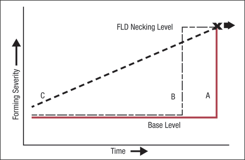 A stamping tears. The forming severity derived from the UTG measurement at the failure zone and at a zero-deformation zone in the stamping is plotted as X in the upper right-hand corner of the graph. This severity exceeds the onset of necking or failure level. The first analysis step: Measure several previous stampings to create a forming history.
