Tears in the stamping indicate a change in deformation or material flow. The current deformation pattern can be defined by circle grids etched into blanks. Leading-edge press shops will keep gridded panels saved from final die buyoffs of stampings. Many shops hang examples of their stampings on the wall—why not make it a gridded stamping?
Numerically determining the deformation difference between the problem and the buyoff stampings provides one definition of the problem. Step two is numerically defining the end target or goal. That information already is available from the gridded buyoff stamping.
Step three: Numerically tracking the corrective modifications. Often, the modifications make the problem worse. These can be rapidly detected and altered before a stamper loses control of its metalforming processes.
Case in Point
An automotive stamping experiencing 100-percent splits during final die tryout illustrates the benefits of three-step troubleshooting. The failure area was located within the product but was fed material from the adjacent binder area. Increasing or decreasing the flow from the binder did not change the severity of the failure. Even more unusual, the amount of binder-metal flow into the critical area did not change the amount of thinning in the critical zone. After weeks of unsuccessful tryout, the stamper assigned a forming specialist from corporate R & D to the project.
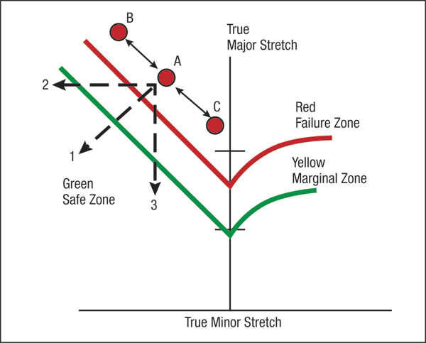 |
| Fig. 2—Both decreasing (B) and increasing (C) metal flow from the binder changed the amount of stretch but not the forming severity. Changing the process along paths 1 thru 3 is required for successful stampings. |
First, our specialist created the circle grid and forming-limit diagram (FLD) to numerically define the formability problem. With 100 percent failures, stretch measurements required a gridded blank taken just prior to failure. Continued formation of the stamping from the start of tearing to the home depth can dramatically change the stretch mode, direction and magnitude. Here, home-depth data are misleading. Incremental (breakdown) stampings determined punch stroke length at initial onset of local necking or failure initiation.
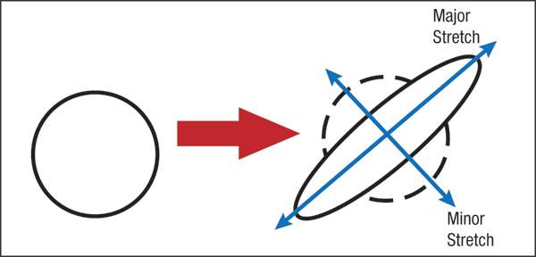
Next, the stamper formed a gridded stamping to that critical depth and made grid measurements. The circles evolve into ellipses (Fig. 1). The long axis represents major stretch, or largest positive stretch, and the minor stretch is perpendicular to the major stretch—this may be positive, zero or negative. For our case study, the critical ellipse A plots on the left side of the FLD (Fig. 2). Its position above the forming-limit curve (FLC) before reaching home depth confirms the very high rate of tearing. Additional gridded blanks were formed with decreased (B) or increased (C) material flow from the binder. This change in flow did not change the forming severity of the stamping. Since the changes along B-A-C were aligned on a constant thinning line (Fig. 2), no change in thickness was expected.
A step-one numerical problem definition:
At a stamping depth 0.75 in. above home, the failure zone major stretch of yy percent by minor stretch of xx percent exceeds the FLC for the tryout steel. Increasing or decreasing material flow from the binder moves the data point up or down along the constant-thinning line, but does not change the amount of thinning or the forming severity (Fig. 2).
The circle grid and FLC also provide data for step two—numerical definition of the end goal or completion target. Fig. 2 indicates that the major/minor strain combinations must move into the green safe zone. For suggested paths 1, 2 and 3, the required final stretch values are automatically defined. Additionally, the grid ellipses indicate the major stretch directions in the material surrounding the failure site. This information highlights the direction of restrained sheetmetal flow. Instead of making blind deformation changes in the deformation zone, specific targeted changes can be made. Changes in workpiece-material properties, lubrication, tool design and other process parameters also can be studied for a new defined end goal. Then, step three—numerical progress tracking—simply requires plotting data points from initial point A toward the goal defined in step two.
Virtual forming or computerized die tryout already provides all of the data needed to implement the three-step troubleshooting process. Leading-edge companies are saving time and money by troubleshooting virtual stampings before machining the first die. MF Technologies: Quality Control