Stuart Keeler Stuart Keeler
President/owner

Let Your Supplier Help

March 1, 2011
0
Comments


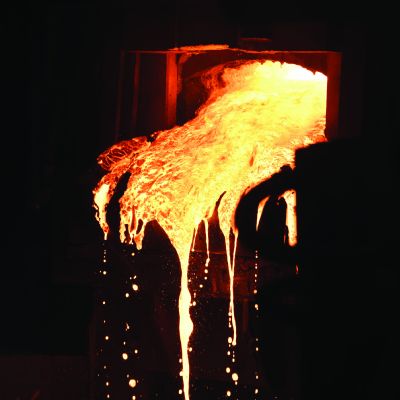
The most productive relationships between suppliers and customers in the metalforming industry are those where partners or team members begin working together early in the design-to-production cycle. Teams might comprise representatives from a sheetmetal supplier and part designer, or tool builder and press shop, etc. Each team member contributes his own expertise to create a more robust product, reduce cost or implement new technology.

Top-notch suppliers bring expertise and data to the table. Many have forming specialists on staff; some have virtual forming ability, to analyze parts early in the design process; and others have created and thoroughly studied new metal alloys or available forming techniques.

In contrast, some supplier/customer relationships remind one of the cold wars. Three examples of these relationships (or lack thereof) are:

• Bad: Adversarial—“My supplier causes all of my problems.”

• Worse: Protectionist—“I don’t trust my suppliers because they might give all of my secrets to my competitors.”

• Worst: Ignorance—“I don’t know who my suppliers are because my end customer purchases the lowest-cost steel for me.”

Know thy Steel—Well

 
Know thy Stell
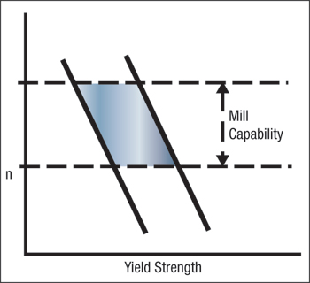
Fig. 1—Mill capability shows the property range expected for a specific steel type and grade.
High on the priority list is correctly identifying the type and grade of sheetmetal required for a given set of tools. Consider this actual case study, using aluminum-killed draw-quality (AKDQ) steel where forming a part required severe stretching. The maximum useable stretch for any steel depends on the work-hardening exponent, or n-value: n-value decreases as a steel’s yield strength increases (Fig. 1). Knowing the distribution curve of n-values for AKDQ steel produced by the supplying steel mill, we can create a set of boundaries—called mill capability, as seen in Fig. 1.

One must be careful to use the correct distribution data. Obviously, steel produced for simple high guard rails will exhibit different properties than will steel produced for a complex-shaped oil pan. Therefore, do not use a distribution curve developed for all AKDQ steel from a given mill for all customer products. Instead, steel mills can provide a series of process codes that details the exact composition and processing parameters used to produce the steel for forming different types of parts. You need the property range for the process code that closely matches the forming requirements of your specific application. If you are going to order steel directly from the mill over an extended length of time, some mills will create special process codes just for your difficult parts.

Yield Strength
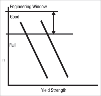
Fig. 2—Engineering window shows the steel property range required to produce a satisfactory part.

Another curve can be constructed that shows n-value limits that will allow forming of an acceptable part (Fig. 2), typically referred to as the engineering window. If n-value is too low the part will neck and tear, and

if n-value is too high the distribution of stretch will change and cause cosmetic defects such as loose sheetmetal, buckling, or low or high spots. Determine the n-value range required by the part by using virtual forming, circle grid/FLC analysis, or via test runs of steel samples having different n-values.

The Final Step

Next we overlay Fig. 1 and Fig. 2 to create Fig. 3—the proper AKDQ steel-product match exists when the engineering window encompasses the entire mill capability. This indicates that all properly made steel should produce acceptable parts.

Unfortunately, this did not happen with the actual case study illustrated in Fig. 3. Here

Fig. 3 Yield Strength
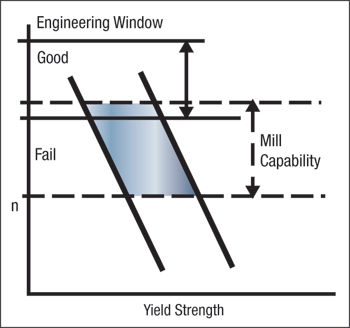
Fig. 3—Overlaying the engineering window and mill capability reveals potential production problems.
the engineering window requires a higher n-value than normally supplied by the steel mill. When the customer tried out the tool in its press shop with a coil of the intended production steel (mid-range n-value), most of the parts exhibited necks or tears—a major problem. The vendor that built and tried out the tool argued it was not his fault because the purchase order simply specified the use of AKDQ steel. The vendor used AKDQ steel from its stock supply, and it made all good parts. When tested, the vendor’s steel had an n-value in the upper 20th percentile of the normal property distribution provided by the steel mill. The steel supplier argued that it had given an honest property distribution and could not be required to only supply AKDQ steel with properties in the upper 20th percentile. The steel supplier did suggest that a vacuum-degassed interstitial-free steel with higher n-values would better fit the engineering window. However, the press shop did not want to pay the extra cost for the steel or for reworking the tooling.

Follow this Procedure

A simple press-shop procedure could have avoided the problem described above:

1) The press shop orders and receives a coil of production steel, and has an independent firm tensile-test the steel to ensure that its mechanical properties are near the mean properties of the mill capability. Don’t assume that coils are shipped with the required properties.

2) The press shop sends half of one coil and a container of the production lubricant to the tool-build and tryout vender, even if it is another department within your own company. Use these coil and lubricant samples during die tryout and buyoff.

3) At final buyoff, perform circle-grid and forming-limit-curve analyses to document that the safety margin is in the green zone. Good parts may be produced, but the process cannot be on the edge of the deformation cliff. This procedure often is performed by the steel supplier at tool vendors making dies for automotive-OEM press shops.

4) When the tool finally arrives at the customer’s press shop, use the other half of the test coil and the same lubricant to check the safety margin of tooling run in the intended home press line—the tool, steel and lubricant were checked out at die buyoff, but the press was different. Also, consider testing the tool in a backup press line. Run this check well before the first production is scheduled. A few press shops have stored coils with the highest and lowest expected n-values, to run extended tryouts. MF

Industry-Related Terms: Alloys, Case, Circle, Die, Edge, Forming, Run
View Glossary of Metalforming Terms

Technologies: Materials

Comments

Must be logged in to post a comment.
There are no comments posted.

Subscribe to the Newsletter

Start receiving newsletters.