Hari Menon Hari Menon
Quality Manager

Dimensional Measurement of Automotive Stampings

May 1, 2012
0
Comments


Measurement systems for automotive stampings can cause controversy through the automotive enterprise, since these systems vary from the body shop to general assembly due to operational efficiency and other requirements. Basically, it boils down to the ‘stamping guy’ not measuring parts correctly, and therefore not providing parts to the right specifications.

Body-shop workers often will check a panel in ‘free state’ based on geometric dimensioning and tolerancing (GD&T), where only the A-B-C datums are engaged and dimensions are taken, with the expectation of the stamping behaving like a rigid body. While die compensation—to bring the dimensional adherence to the requirements to the GD&T—has developed by leaps and bounds, the expectations of the body folks often are unrealistic, though it clearly is getting closer to the requirements for clamping the secondary datums.

This is stated as a prelude to the following discussion of various measurement systems, since proper use of GD&T to datum a part is significant to the success of the measurement system.

In a die shop or stamping plant, two important measurements must take place. First, part measurements must be reliable, repeatable and accurate. Then we need a system to accurately measure the dies, enabling the use of the data to generate offsets to the surfaces measured. This process will allow the end product to be manipulated to provide a stamping that meets design requirements and, therefore, eliminate assembly issues. The holy grail of measurement systems is to develop one system for the stamping plant that can potentially perform all of the required functions with reliability, repeatability and accuracy, while being highly flexible to enable the user to obtain the measurements he desires shortly after the need for the measurement is determined.

Here we present the pros and cons of a few of the most common dimensional-measurement systems.

Feeler, Step and Pin Gauges, and Hole Position/Size Templates

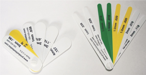
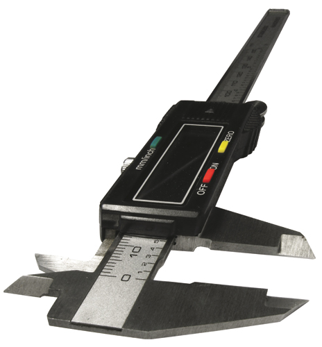
Feeler and step gauges (shown here) offer simplicity when measuring stamped parts, providing the die maker and the stamper a good sense of the dimensional accuracy of
a panel.
This is the simplest form of stamped-part measurement, providing the die maker and the stamper a good sense of the dimensional accuracy of a panel. While this type of measurement approach typically is simple, the designer/manufacturer of the checking fixture must plan to include rails around the part to enable the use of feeler/step gauges around the panel. This technique enables relatively quick measurements, and allows inspection wherever rails are available—critical for areas of components where parallelism matters, such as door outer edges.

A significant disadvantage of this measurement method is the cost incurred to build rails onto fixtures, and the lack of documentation. Over the life of a typical fixture, its use typically will diminish as the stamped product attains dimensional stability. A significant portion of part measurement takes place during die verification and tryout, during which the process stabilizes and the part requires less frequent inspection. Also, we often see use of hand-written documents (sometimes scanned into electronic files) to document these measurements, not ideal for entering results into a database for future access. One other significant disadvantage: the lack of repeatability and reproducibility, since these techniques are highly operator dependent and require extensive operator training.

Electronic Data Collection Using “Datamytes”

Though a number of such devices are available, the term “datamyte” has practically become a generic name for the use of a bushing and an electronic transducer to check panel dimensions. The transducer makes physical contact with the part and the dimensions are collected in a database for future analysis using statistical tools such as x-bar and r charts that enable tracking of results over a specified period of time. The process takes less time to complete than does use of feeler, step and pin gauges, requires less operator skill, and allows for a high degree of repeatability and reproducibility.

The term “datamyte” has practically become a generic name for the use of a bushing and an electronic transducer to check panel dimensions. The transducer makes physical contact with the part and the dimensions are collected in a database for future analysis using statistical tools such as x-bar and r charts.
Using a datamyte, the process designer must plan for the use of transducers and budget for the cost of the bushings. Also, these standardized transducers allow the user to check part quality only at predetermined, discrete positions, which makes it impossible to measure a part for V-gaps or any changes in the profile along its length. Hole sizes are not easily measured, and hole positions must be measured with templates.

CMMs

…have long been the tools of choice to verify that a finished stamping meets design criteria at numerous discrete points. A CMM does have significant advantages in terms of ability to reliably, repeatedly and accurately measure the part dimensions required to verify a stamping’s integrity. The checking fixtures used for measuring parts on a CMM are not complex, and staging panels for a CMM check typically takes little time. Lastly, CMMs can be used to certify a fixture or take dense dimensional data for a die.

Some disadvantages to the use of CMMs: They only provide discrete data, and results are not very visual. When using a CMM for the physical measurement of a die, the user may find it difficult to obtain a machine file using the data collected.

Gaining ground in stamping plants and die shops is use of portable CMMs. These compact and flexible devices can be moved to the location where data is needed, and can prove extremely handy for quick reviews on the shop floor. Many of these devices combine scanning (using red light) with the use of touch probes.

White-Light/Blue-Light Scanning

White- and blue-light scanning systems have become the Holy Grail for many stampers during the last 10 years or so, although many tool and die manufacturers have yet to adopt the technology. The most significant gain in using these scanners is the highly visual 3D representation of the part, which allows the user to almost instantaneously evaluate the parts. Here again, value is obtained by evaluating the panel following all of the GD&T rules; violating the rules can result in instantaneous misrepresentation of panel quality. An added benefit of these systems is the significant cost reduction of the simplified checking fixture used. Data can be quickly translated into a machine file with compensation to correct any die issues that may be causing dimensional issues in the body shop.

White- and blue-light scanners commonly find use for:

1) Panel checking—The typical considerations are accurate part measurement within the tolerances provided by GD&T, although tolerances typically have changed to the extent that finding tolerances of + 0.1mm on any given part is not uncommon.

2) Die checking—This allows the reengineering of dies by scanning an existing die, either for duplication or for recutting a damaged die.

3) Scanning of castings—This practice can eliminate the unproductive and wasteful air cutting that can occur in machine shops.

The development of blue-light (LED) technology for panel scanning represents a significant step in the right direction for this technology, since the data is less affected by ambient lighting and significantly improves the quality of the data collected.

Data collected from scanners is not instantaneously available, since there is considerable setup time on a nonautomated, manually operated system. And, a scanner attached to the end of a robot is limited to scanning panels that already have been set up.

Which System is Best?

None of the systems described here meet all of the requirements of speed, data quality and coverage of the panel or die. White/blue-light scanning seems to be the process of choice for most die manufacturers and stamping houses. In particular, the advent of blue-light scanning systems seems to bring the scanners closer in ability to the dimensional accuracy of a CMM. However, portable CMMs will continue to find use for comparison purposes, to ensure that the data reflects what is seen in the body shop.

The use of rails, calipers and step, feeler and pin gauges will continue to play a significant role in applications requiring quick measurement of panel dimensions, but most fixtures will have limited rails around them. This will allow stamping plants and die shops to make quick decisions while waiting to obtain data from CMM or white/blue light inspections. MF
Industry-Related Terms: Datum, Die, Fixture, Form, Reproducibility
View Glossary of Metalforming Terms

Technologies: Quality Control

Comments

Must be logged in to post a comment.
There are no comments posted.

Subscribe to the Newsletter

Start receiving newsletters.