Stuart Keeler Stuart Keeler
President/owner

A Different Look at Friction

September 1, 2010
0
Comments


Remember the so-called “good old days” of metalforming? An acceptable stamping held water or had no smiling tears. Both the low-strength rimmed and aluminum-killed steels had only about 2 or 3 deg. of springback in a bend. For welding two pieces together, this amount of springback was corrected by a strong clamp.

Applications with higher strength steels required stronger clamps. Often a hammer blow replaced the clamps for unexposed applications. Eventually forming transitioned from the two-step process of “form it—then fix it” to the single-step process of “form it correctly in the press.”

Schematic of draw bead simulator
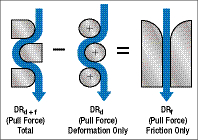
Fig. 1—Schematic of draw bead simulator (DBS) using two test stages for determining coefficient of friction (COF).
Springback compensation procedures created by extensive trial and error became secret weapons for press shops. Since springback is proportional to yield strength, sheetmetal specifications were tightened to reduce the acceptable range of yield strength and other mechanical properties. The thought was reducing the incoming material variability would reduce the final product variability.

Unfortunately, incoming sheetmetal is only one of the input variables to the forming system. What about the lubricant? If consistency of the incoming metal is a highly desired goal, then consistency of the lubricant and its application should be an equally desirable goal. But how are lubricants treated in too many press shops? If a stamping is in trouble, the first reaction is to modify the lubricant. Apply a thicker or thinner layer of lubricant. Add more solids or more water. Change the type of lubricant. Combine several types of lubricants for difficult problems—mix some graphite and grease. Most of you are aware of what really happens. Now instead of lubricant changes, press shops realize that the lubricant and its application are a system input that can easily be kept constant and even utilized to minimize the effects of other input inconsistencies.

An extensive study of the effectiveness of lubricants under different forming conditions was conducted using a draw bead simulator (DBS). Draw beads are used to control the flow of metal from the binder area over the die radii and into the die opening. Because of the severe bending and unbending through the draw bead, the DBS, designed by Dr. Harmon Nine of the GM Research Center, was an excellent tool to study the coefficient of friction (COF) of the sheetmetal.

DBS data showing electrogalvanized steel  
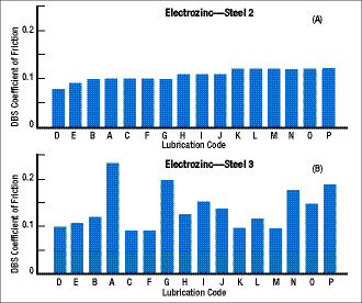
Fig. 2—DBS data showing (A) electrogalvanized steel 2 is
relatively insensitive to type of applied lubricant, while (B) shows high sensitivity of electrogalvanized steel 3.

The procedure to determine the COF is shown in Fig. 1. A strip having a known quantity of lubricant is drawn through a set of standard, fixed draw beads. Keeping the bead diameter constant means the amount of bending and unbending is constant. However, the force to pull the strip through the fixed beads (left sketch) is the sum of the deformation and the friction forces. Replacing the fixed beads with roller beads (center sketch) allows measurement of only the deformation force without the friction component. Subtracting the two forces (right sketch) provides the frictional force and calculation of the COF. This test allows evaluation of different materials, lubricants, draw bead metals, test speeds and all combinations of these four variables.

The August 2010 Science of Forming column described how the COF of electrogalvanized steel could vary greatly depending on the characteristics of the production coating line. DBS tests also showed some interesting COF results for these same steels. Fig. 2 presents test results for electrogalvanized steel from two different steel producers (codes 2 and 3). These two steels were tested with 16 different lubricants ranging from very poor (lubricant A—very thin layer of flex rolling oil) to excellent applied lubricant.

 DBS Coefficient of friction
 Fig. 3—Lubricant A from Fig. 2 shows a high COF at low forming speeds.
The difference is obvious. Steel 2 has a narrow range of COF values for a wide range of lubricants. Numerous lubricants applied to steel 2 have the same value of COF. This electrogalvanized steel would be characterized as stable or robust.

Steel from producer 3 reacts completely different. The COF is very sensitive to the applied lubricant. Changing the lubricant can triple the value of the COF. This leads to several conclusions. Using steel from producer 3 means one must carefully choose a lubricant with a low COF. This allows blank size and configuration or draw bead height to control material flow. A high COF lubricant probably would place the stamping near the edge of the deformation cliff with little opportunity to design control parameters of the blank. It also suggests that when steel 3 is used for different stampings, the same lubricant must also be used to achieve more predictable stampings. Using different lubricants with different COF would create dimensional variations similar to large differences in mechanical properties of the incoming metal.

Additional DBS tests (Fig. 3) were conducted at different test speeds of the strip through the draw bead. Tested was steel 4 (hot-dipped galvanized alloy—galvannealed) with a steel draw bead and lubricants A and C from Fig. 2. The results show that using lubricant A at slow forming speeds would create a COF greater than 0.30. A repeat of the test resulted in the strip locking in the bead and tearing without any movement. The computed COF for this failure was 0.35.

In contrast, the low COF lubricant C showed very little increase in COF at very slow forming speeds. Ask most press shop personnel if they ever form sheetmetal at speeds of 0.15 in./min. and almost all will reply, never. Again, stop to analyze the forming process. At the beginning of the forming operation the blank must increase from no motion to the forming speed—passing through the 0.15 in./min. speed range (high COF). The reverse happens at the end of the forming process. Unfortunately, that is reverse of what the metal should be doing. One really wants a low COF to permit blank motion to start easily. The high COF should come later in the stroke to control metal flow. At the end of the forming process, with the stamping having high strain and near the edge of the deformation cliff, the worst condition is a high COF locking the sheet just when it needs to flow freely to complete the stamping.

Friction can be our friend or enemy. It all depends on understanding how to choose the proper lubricant and then making it behave the we need it to. MF

Industry-Related Terms: Blank, Center, Die, Draw, Edge, Form, Forming, Layer, Solids, Stroke, Bending
View Glossary of Metalforming Terms

Technologies: Quality Control

Comments

Must be logged in to post a comment.
There are no comments posted.

Subscribe to the Newsletter

Start receiving newsletters.