


Stampers must thoroughly understand this formula and its application. The most common mistakes we see when applying the formula come from a lack of understanding of the brake-monitor setting, and the application of the depth-penetration factor.
The Brake Monitor
A control-reliable device, the brake monitor measures the elapsed time from the initiation of the stop until the eventual actual halting of ram motion. With nearly all solid-state controls, when the press stops the monitor measures the elapsed time and compares it to a maximum allowable value preset by the press manufacturer. If the time exceeds the monitor’s maximum value, the unit produces a fault that prevents the press from being stroking without an operator first resetting the fault. Press manufacturers set the brake monitor to a point greater than the actual average stopping time of the press. Thus, as the brake gradually wears the machine does not instantly fault and render the press unusable until the stamper adjusts or replaces the brake. Instead, this built-in allowance enables most presses to operate for several years before reaching the limit. With regular checks by maintenance, the brake’s gradually degraded performance should be detected well before it reaches the limit and a stamper should never experience unplanned downtime due to brake wear. Should the brake wear before maintenance is performed, the measured stopping time will exceed the limit and a brake-monitor fault will be initiated.
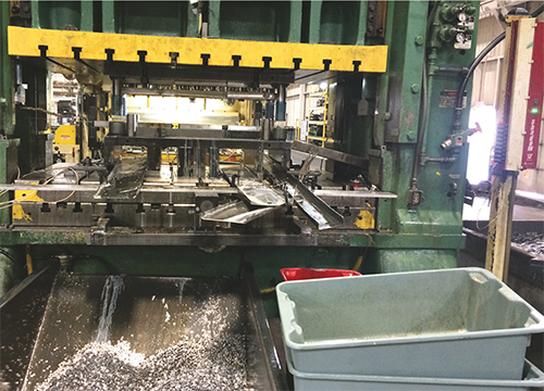
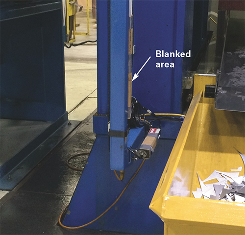
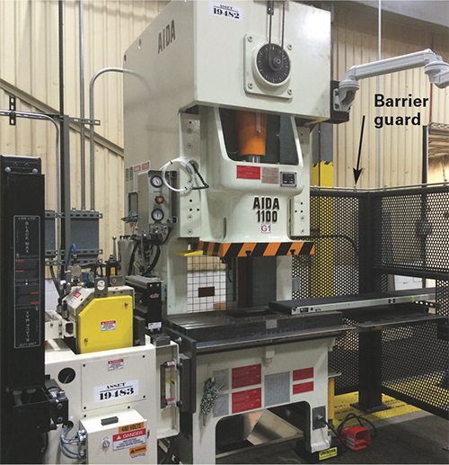
The maximum actual measured time value the brake monitor will accept without faulting is a critical portion of the stop time formula. That brake-monitor limit determines the proper placement of the light curtain, not the average stop time measured when installing the light curtains. Take care to place the light curtains at or beyond the distance that the formula deems as safe when the stop time reaches the maximum brake-monitor limit. This protects operators as braking time gradually increases. Depth Penetration Factor This factor relates to the light curtain’s MOS and varies depending on the proximity of the emitters and sensors in the transmitter and receiver. Some small objects may go undetected if entering the field between the individual beams. Picture finger tips passing through an open window blind—the left-to-right slats of the blind are analogous to two adjacent beams of light. There is a distance between the beams where a small object (possibly even an operator’s fingertip or hand) can enter the sensing field without detection. The MOS defines how small of an object always will be detected by the light, regardless of where it enters the sensing field. Additionally, most modern light curtains enable the user to intentionally turn off, or blank, a portion of the curtain. This allows chutes, conveyors or other items pass through the sensing field when required for production. Light-curtain manufacturers publish the MOS of their devices with no beams blanked, and the increased MOS that results with one or more adjoining beams blanked. The ultimate MOS will result in an additional distance the light must be moved away from the hazard beyond that defined by the formula used to calculate the safe distance. Industry experts, to account for the fact that MOS varies, developed the Depth Penetration Factor as a way to calculate the additional distance the light’s sensing field should be from the hazard to safeguard the operator. The end user must first define the line of hazard—the point nearest the operator where the action of the press creates a hazard. The light-curtain installer, then, places the curtain’s sensing field at least as far from that line as the safety distance calculated using the prescribed formula. Often stampers will use the edge of the bolster as a default for this line of hazard, which makes it easy to monitor—any tool that fits inside of the bolster complies with the guarding. In applications where the tooling never extends to the edge, though, it is acceptable to define the line accordingly. Production Issues and the MOS Too often, even when stampers factor in the stop time and brake-monitor setting, they fail to sufficiently consider production issues that may require the MOS to increase. To correctly apply light curtains, stampers must examine all of the factors required for production. For example, the workpiece material must be brought to the point of operation, and the stamped parts, as well as the scrap from punching and trimming, must exit the point of operation. The guarding must account for these actions. An excellent option that allows proper scrap egress while continuing to protect operators is the use of a guarding zone (photos D-E). Here, physical barriers prevent access to the hazard except through the opening between them, and light curtains scan across the opening to prevent human entry without blocking the lights. The lights are set up with manual-reset fault logic. Once interrupted, even for a moment, the lights remain in fault condition even when unblocked; an operator must use a key to reset the lights and allow the machine to run. The next biggest offender we see in the field: improper guarding of the press where the parts exit. The opening through the guarding—whether a light curtain or physical barrier—must be large enough to allow the parts to escape. Referring again to Photo B, the stamper has adjusted the opening at the exit end of the straightside press to allow for part egress, which, unfortunately also allows an easy reach into the hazard through the window. Similarly, on gap presses, the part often exits on the side opposite the feed, which creates a similar hazard. Cause and Solution The underlying cause for these types of part-egress issues often traces back to using gravity to move parts away from the tooling. This necessitates an aggressive slope to the part chute that requires the stamper to locate the opening in the guard very close to the hazard. Developing a solution, the stamper must first determine the required opening; the larger the opening the further it must be from the hazard (refer to OSHA standard 1910.217 Table O). In a practical sense, the opening must be far enough away from the hazard to prevent an operator from reaching through the opening into the hazard. This, however, may result in the opening being too far away to use a chute and gravity to move parts out. The answer: Use conveyors to remove parts from the tool and through the guarding. With a gap press, this may require additional barrier guarding extending out from the machine frame, and then forward to the front light (photo F). With a straightside, the stamper might have to add a fabricated-sheetmetal tunnel that extends out from the frame so that the opening can be located far enough away from the hazard to ensure safety (photos E and G). Preventing Reach-In The last issue to address involves preventing operators from reaching around the light curtain or moving between the curtain and the hazard when the light curtain has been positioned away from the press. Additional safeguarding is required, such as installing an additional section of light curtain that fills the area between the vertical curtain and the hazard. In Photo G we see side panels installed to prevent reaching around behind the curtain. And, additional sections of light curtain have been added. Fortunately, when stampers diligently consider the issues outlined here when designing a press-guarding scheme, they will enjoy optimum productivity without sacrificing safety. MF
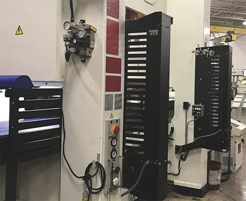
D and E—Physical barriers, positioned along with light curtains using a manual reset, create a guarded zone that protects the rear of the press. In this case the light curtain is 5 ft. from the hazard. An entire scrap bin can fit inside the zone, easily accommodating scrap without compromising safety. Workers approaching the rear of the bolster must pass through the light curtains, which will enter a fault state and remain faulted until the personnel exit the area and reset the lights with a key.
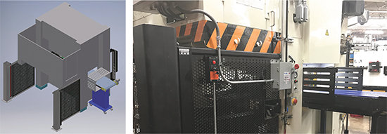
F—Vertical light curtains with horizontal remote segments protect the front of the hazard. These photos were taken during installation; not shown is additional guarding added later to prevent reach from the feed side. An L-shaped barrier extends from the right side so that the part-escapement hole allows tall parts to escape while still being far enough from the line of hazard to protect the operator. This requires the use of a conveyor to bring the parts from the tool out through the guard.
Note: All barriers mount on heavy wall 8-in.-square posts anchored to the concrete. Mesh barriers comprise ¼-in.-thick perforated-steel panels.
G—This vertical light curtain includes a remote segment protecting the area between the curtain and the press. Note the heavy-duty brackets and how the light-curtain elements are protected from damage during die loading; the side panels that prevent reach into the hazard behind the curtain; and how the height of the curtain prevents reach over the top or from underneath.
View Glossary of Metalforming Terms
Technologies: Safety
Comments
Must be logged in to post a comment. Sign in or Create an Account
There are no comments posted. Safety
Toolroom Safety
Peter Ulintz Monday, September 25, 2023
 Stamping Presses
Mexico Stamping Technology Webinar Series 2023: Day 2
Thursday, March 30, 2023
 Webinar
  Safety
Pilz Digital Maintenance-Safeguarding System an Efficient Al...
Thursday, March 16, 2023