Finally, the elastic deflection stored in the press frame dissipates through high-frequency oscillations occurring between points E and F.
The Impact of Negative Tonnage on Die Design
High-tensile unloading forces introduce large downward accelerations to the upper die half. These forces essentially work to separate the upper die from the bottom of the ram on every stroke. Insufficient force of the hydraulic die-clamping system or mechanical clamping could cause the upper-die half to separate from the bottom of the ram on each stroke, causing fatigue to the upper-die mounting fasteners.
Uncontrolled, high reverse loads can fatigue the press structure. Fatigue-related cracks can propagate in the slide, drive linkage, crown, uprights and bed. Eventually, this results in a catastrophic (sudden) fatigue failure. Reverse loads also have been associated with quality issues due to premature wear of punches and dies.
 Most presses are designed for approximately 10 percent of their maximum-rated forward load in reverse tonnage (check with your specific machine builder). For example, an 800-ton press with 10-percent reverse-tonnage rating should not exceed 80 tons of reverse load.
A press equipped with a suitable tonnage monitor can measure reverse load. Unfortunately, during the die-design process, tonnage-monitor data are not available. Instead, the die designer must estimate the reverse tonnage to ensure no overloading of the selected press, sufficient holding force of the upper-die clamping system and no damage to the die itself.
Estimating Reverse Tonnage
The ratio of material yield strength (YS) to ultimate tensile strength (UTS) was reported to be a critical factor in determining the amount of forward tonnage converted to reverse tonnage when blanking in a press (Wonsetler and White). Empirical tests were conducted to predict the unloading force (Fu) as a function of the YS/UTS ratio:
Fu = [0.893 (YS/UTS)2 ] + 0.107
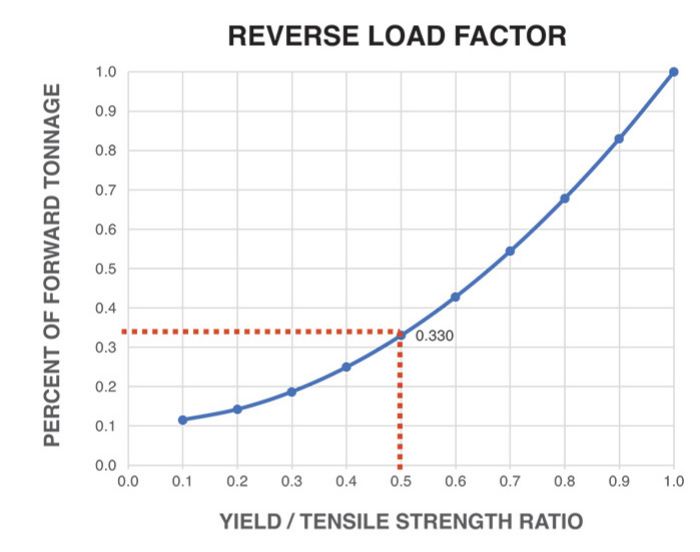
When plotted as a graph, the strong relationship that the ratio of yield strength to tensile strength has on reverse loading can be observed (Fig. 2). Use this graph to estimate the reverse tonnage produced by a blanking process without dampers.
Assume a 24-in.-dia. blank produced from 0.182-in.-thick steel with 30,000 psi YS and 60,000 psi UTS. The YS/UTS ratio here: 0.5.
Find the reverse-load factor from the curve for 0.5 YS/UTS ratio. This example yields a reverse-load factor of 0.33.
Next, estimate the force (tonnage) required to produce the blank:
P x t x Ss/2000 = 308.7 tons
where
P = part perimeter (24 in.)(π) = 75.40 in.
t = material thickness = 0.182 in.
Ss = material shear strength = 45,000 psi
Obtaining accurate shear stress data (Ss) is quite difficult; thus, we use approximations. The approximate shear strength of mild steel measures between 70 and 80 percent of its tensile strength. The above example used 75 percent.
Now multiply the estimated blanking force by the reverse load factor:
308.7 x 0.33 = 101.87 tons
The result must be less than the rated capacity of the press in reverse load.
An 800-ton press with a 10-percent reverse-tonnage rating would be overloaded in reverse tonnage (101.87 tons) even though the blanking tonnage (308.7 tons) falls well within the forward-tonnage rating of the press. This is critical information for the die designer as the proposed process must change.
Here, the designer has several choices.
Shear can be added to the die cavity to reduce the blanking tonnage. The force would need to be reduced to at least 200 tons. A reverse load factor of 0.33 would result in a reverse load of 66 tons. Within the rated capacity of the 800-ton press, this amount also leaves a margin of safety for die wear, which will increase the blanking force.
Or, add approximately 80 tons of counterpressure inside of the die using nitrogen or hydraulic cylinders. Shock dampers mounted to the press bed—outside of the die—provide another option. Any counterpressure—inside or outside of the die—proportionally increases the blanking tonnage. Be sure that the increased force does not exceed the rated capacity of the press. Adding 80 tons of counterpressure in our previous example increases the blanking tonnage to approximately 389 tons and the reverse tonnage to 128 tons. But the 80 tons of counterpressure counteracts this 128 tons, resulting in 48 tons of reverse load.
The final option: Select a different press with greater reverse-tonnage capacity. MF
Technologies: Tooling


 Peter Ulintz
 The Y axis depicts press force in terms of forward (positive) tonnage and reverse (negative) tonnage. The dashed horizontal line represents zero tons. The X axis represents cycle time in milliseconds (ms). The curve shows the rapid buildup and release of press forces with respect to time during the working portion of the press cycle.