 George Keremedjiev
Understanding Sensors & Error-Proofing, Part 2: Failure Modes for Photoelectric Sensors
May 1, 2016Comments
Frustrating to many a metal stamper is the seemingly magical reaction that photoelectric sensors can have to a moving stamped part. The sensor salesperson assures you that this particular sensor will detect your stamped part—even as that part exits the die rotating and gyrating into various flight paths on its way to the container. So, the sensor is purchased and mounted on the die to detect the exit of the stamped part. All seems to be okay for several hours, perhaps even for a full day’s run. Then it starts…a seemingly random and intermittent series of nuisance stops. The operator checks the die and sure enough—the part did exit but somehow the sensor failed to detect it. Why would the process work for many strokes of the press and then, with no apparent change in that process, the sensor fails to detect the part?

Fig. 1—This part, with multiple hole features and a unique shape, demands careful testing of photoelectric sensing before installing sensors in the tooling.
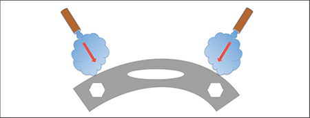
Fig. 2—Copper tubes provide air blasts to eject parts from the die.
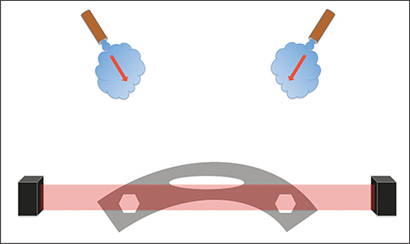
Fig. 3—Here’s a typical through-beam photoelectric setup where a transmitter emits a beam of light across the exit path of the part to the receiver. The transmitter and receiver mount on the end of the die.
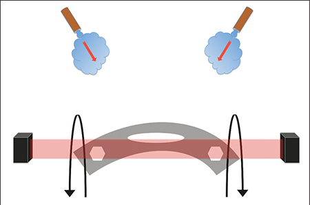
Fig. 4—Assuming equal and symmetrical bursts of air from the copper tubes, the part may start to rotate vertically about an axis (as shown by the two arrows). This rotation could drastically reduce the amount of part-material cross-section within the beam of light. This reduction may be random and unpredictable.
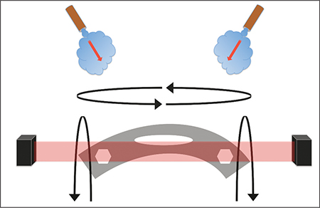
Fig. 5—If the air bursts are not of equal force, the part could start to spin about a second axis (as shown by the left-to-right/right-to-left circular arrows).
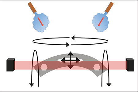
Fig. 6—Shock and vibration of the press and die can introduce unpredictability (signified by the centered arrows).
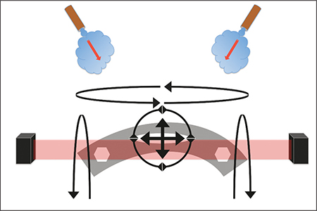
Fig. 7—This illustration depicts the part rotating left-to-right or right-to-left in a circular pattern. When combined with previously described multiple axes of rotation, this circular motion can prove indecipherable to a photoelectric sensor.
The sensor salesperson assured a flawless application, and it sure seems that way for 99.9 percent of the time. But production floors view that 0.1-percent failure rate with disdain, and rightly so as it can translate to dozens of nuisance stops in a given day. What to do? How to simulate all possible part position on a test bench to eliminate even the slightest possibility of a blind spot in a million possible exit configuration for that part? How should one test for conditions that seem impossible to predict? There is a way.
Consider Part Rotations, Orientations As they Exit Dies
Imagine a World War I biplane putting on an acrobatic performance in an air show. That’s akin to what happens to a stamped part as it exits the die. To help visualize this, consider a representative part in Fig. 1. The small, stamped bracket with three holes—two hexagonal holes on the ends and one oval hole in the middle—has a cross-sectional thickness of 0.040 in., with the holes accounting for about 20 percent of removed material. Let’s explore this part’s various motions as it exits the die, and how these motions are captured, or not captured, by the photoelectric sensor.
Fig. 2 shows two copper tubes using air blasts to eject parts from the die. The copper tubing is symmetrical and well-aligned with the part. This, of course, is not the case for many dies. Setters and operators make their favorite adjustments to the tubing, bending it in whatever manner necessary to get the parts out of the die. But for our purposes, assume that the two puffs of air are synchronized and that the parts eject symmetrically—exiting on a parallel path to the tooling.
Fig. 3 shows a typical through-beam photoelectric setup where a transmitter shoots a beam of light across the exit path of each part to the receiver. The transmitter and receiver mount on the end of the die. Ideally, the transmitter and receiver would be mounted within blocks of steel or aluminum to protect from damaging blows as the die is moved about the shop and serviced in the toolroom. The 0.040-in. part thickness is well within the detection capabilities of the photoelectric sensor. What could possibly go wrong?
Fig. 4 depicts the first challenge to the sensor’s capabilities. Assuming an equal and symmetrical burst of air from the two copper tubes, the part may start to rotate vertically about an axis (as shown by the two arrows). This rotation could drastically reduce the amount of part-material cross-section within the beam of light. This reduction may be random and unpredictable. There may even be circumstances where the rotation only presents the crown above the oval hole of the part to the light beam as the upside-down part exits the die.
What if the two air bursts are not of equal force. As Fig. 5 shows, the part could start to spin about a second axis (as shown by the left-to-right/right-to-left circular arrows). In this case, the part may shoot out of the die lengthwise, presenting a minimum amount of solid metal to the light beam. However, the very next part, with a different angle of rotation, would offer much more metal within the light beam…an unpredictable situation.
Shock and vibration of the press and die also can introduce unpredictability (Fig. 6). The part may jiggle as it leaves the die, and this could present material to the light beam that is not stable on the X and Y axes of vibration, making the oval and hexagonal openings truly variable and unpredictable within the light beam. Fig. 7 depicts the part rotating left-to-right or right-to-left in a circular pattern. When combined with the previously described multiple axes of rotation, this circular motion can prove indecipherable to a photoelectric sensor.