Review your
die maintenance and quality control (QC) records to identify other problem
areas. If you find recurring die malfunctions or quality problems, plan to
install sensors to detect them also.
 Keep in mind
that some problems require multiple sensors for detection. For example, you can
detect pulled slugs by installing sensors in the bottom die under each corner
of every spring stripper. Transfer operations are also sensor-intensive,
typically requiring two sensors per station. Select a die protection controller
with enough inputs to monitor what you anticipate being your most heavily
sensored die, plus a few spares.
Keep in mind
that some problems require multiple sensors for detection. For example, you can
detect pulled slugs by installing sensors in the bottom die under each corner
of every spring stripper. Transfer operations are also sensor-intensive,
typically requiring two sensors per station. Select a die protection controller
with enough inputs to monitor what you anticipate being your most heavily
sensored die, plus a few spares.
Ensure that
the controller has sufficient setup memory to store setup information for all
the dies that can be run in each press. The controller should also provide a
way to conveniently back up your settings, as it can take years to create
settings for all your dies.
Modern
resolver-based controls are precise and fast. Resolver timing signals are
typically accurate to one-third of a degree of crankshaft rotation. It is
important to choose a high-speed die protection controller even if you run at
low to moderate speeds. This is because some sensor actuations are short,
regardless of how fast the press is running. Picture an air-ejected part flying
past a photoelectric sensor. Such a sensor signal may be less than 10 ms in
duration.
Ensure that the control system has the monitoring logic needed for your applications. Some sensors need to be monitored continuously to make sure they are always off, such as for material buckle; or on, such as to detect the end of material. Some sensors should have brief, momentary actuations during a specific timing window such as for part ejection, while others should stay actuated for a specified portion of the cycle. This would apply to detect material feed until the pilots have captured the strip. Still others should be monitored so that they are actuated only during certain portions of the cycle—especially sensors that monitor things such as side-action cams, transfer mechanisms, and air cylinders.
Finally, in
addition to the expected failures, your control system should be able to detect
malfunctioning sensors, such as when a cyclic sensor is shorted or otherwise stays actuated for an entire stroke. For example, if a part fails to fully eject, but instead “sticks” in front of the sensor, the controller needs to have the ability to determine when a cyclic sensor fails to cycle. This is often called “fail-safe detection.”
2. Develop a Sensor Connection Scheme
Sensors must
be connected to the controller.
Press-mounted
sensors that are
used on every job, such as material buckle and end-of-stock sensors, can be
hard-wired to the controller permanently. These sensors do not change from job to
job, so there is no need to provide a means to connect them at run time.
Die-mounted
sensors are a
different story. When a die is changed, sensors such as those detecting part
ejection, misfeed, stripper position, cam return, and so forth need to be
connected to the controller during setup. It is impractical to wire die-mounted
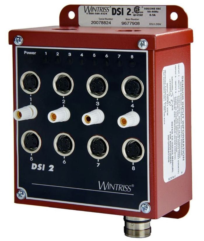
sensors directly to the controller. Instead, a press-mounted sensor interface
device is wired to the controller and placed close to the die area.
Typically,
these devices feature connectors to accept individual sensors, as well as a
master connector that enables power and sensor signals from an array of sensors
to connect through a single cable. This is usually done from a die-mounted
junction box. In addition to being a convenient connection point for the sensors,
the interface device provides 24-VDC power for electronic sensors. It may
feature pulse-stretching for short sensor signals. Also, the interface device
may offer impedance-matching circuitry to enable the use of simple electromechanical
sensors such as spring probes with water-based lubricants.
Importantly,
something as seemingly trivial as die wiring can make or break the entire
implementation process. Poor wiring practices can ruin an otherwise
well-planned die protection program. There are two ways to connect die-mounted
sensors to the interface device.
The first, called
the traditional sensor connection method, which uses individual sensor connectors
on the interface device, is troublesome. This inefficient wiring scheme
requires each sensor to have a length of cable attached to it that is long
enough to reach the press-mounted interface. When the die is not in use, these
permanently attached sensor cables are hastily coiled up and stored with it. At
run time, they are uncoiled and plugged into the press-mounted interface.
Sensors more often need to be replaced because of damage to the cables than all other sensor failure reasons combined. In addition to the possibility of catastrophic physical damage to a loose cable, it is critical to consider cable “wear.” In this context, this does not refer to abrasion, but rather, to work hardening. Most sensor wires are made from copper, which work-hardens quickly. Work hardening occurs when a metal is cold-bent repeatedly. Each time a cable is flexed, the copper wires inside become harder, more brittle, and will break inevitably. It is the repeated coiling and uncoiling of the sensor cables that will cause failure.
The traditional
method of connecting one sensor at a time also is inefficient. The setup
operator needs to ensure that each sensor is plugged into the correct input. Mistakes
can lead to nuisance stops and die crashes.
The second, best-practice
connection method is to use an intermediate die-mounted junction box to which
all the sensors are permanently wired. The die-mounted box is plugged into the master
connector on the press-mounted interface through a single, easily replaceable
cable. This eliminates wiring errors and sensor cable wear. Standardization is
important here. You should use the same setup on every die and every press.
You can
purchase a die-mountable junction box, or you can make your own with an
enclosure, terminal strip, and connector. Either way, be sure to select
components and devices that can withstand the rigors of in-die use. If the
sensors are installed in the die in such a way that they must be removed when
the die is serviced, consider using a die-mounted junction box with connectors
for the individual sensors. That way, you will not have to disconnect and
reconnect wires on a terminal strip each time the die undergoes maintenance.
Junction boxes
should be located on the die in such a way to protect them from accidental
physical damage while the die is being handled. Placing the junction box on top
of the lower die shoe is better than installing it on the side of the die or
underneath it.
3. Set Up a Sensor Lab
Companies
embark on die protection implementation programs with varying levels of
success. Whether it's a big-budget, plant-wide program involving a team of
people or a one-person pay-as-you-save ROI-based implementation, some programs
succeed while others fail. All programs and approaches are a little different,
but there is one step in common among the successful users: Bench testing.
 The best way
to ensure that a sensor will work in the die is to try it out on the bench
first. A well-stocked sensor lab will likely pay for itself the first time that
one of those good-on-paper ideas proves to be ineffective in practice. The
worst (and most expensive) place to prove out sensors is in the press when the
die should be in production.
The best way
to ensure that a sensor will work in the die is to try it out on the bench
first. A well-stocked sensor lab will likely pay for itself the first time that
one of those good-on-paper ideas proves to be ineffective in practice. The
worst (and most expensive) place to prove out sensors is in the press when the
die should be in production.
Your sensor
lab should be in a quiet area of the plant. Many are in the QC department. It
should be equipped with the following items:
- 24-VDC Power Supply. Virtually all die-protection
controllers are 24-V systems, and nearly all electronic sensors can run on 24 V.
To test sensors, you need to power them.
- Voltmeter. Most electronic sensors feature LEDs
that illuminate when the sensor is actuated; however, sensors often are installed
in mounting blocks that make it impossible to see the indicator. A voltmeter
will show you when a sensor actuates.
- Accurate Positioning Device. Selecting a mounting location for a
sensor required to detect material feed to within +/- 0.005 inch (in). cannot
be done by the human eye. A 3-axis, micrometer-controlled staging table
provides the precision needed to ensure that sensors will be installed in the
right place.
- Extensive Sensors Inventory. There’s an old saying: “When the only tool you have is a hammer, every problem starts to look like a nail.” If your bench-testing regimen is based on a limited number of sensors, you will be far more likely to select a marginal solution and shoehorn it into an application. An extensive selection of sensors for the test bench enables you to keep looking when something isn’t quite right.
4. Establish Application Guidelines
Die
protection programs will almost always fail if nuisance stops are
allowed to occur on your machines. A nuisance stop is a machine stoppage that
is initiated by the die protection system even though no real problem exists.
 Nuisance stops almost always result in eventual die damage—but not directly. They cause machine operators to lose confidence in the system to the point where they will ignore real errors. In some cases, the nuisance stops are frequent enough to adversely affect production, and the operators turn the entire system off.
Here
are some common causes of nuisance stops and how to avoid them.
- Sensors that must be installed at run-time. The only two things a press operator should have to do to set up the die protection system are to select the correct program on the control and plug in a single cable. If the operator is required to locate, install, and adjust sensors that you move from die to die, the likelihood of a correct setup drops precipitously. Rather than moving a sensor from die to
die, permanently install a sensor on each die that needs it. Compared to die
crashes, sensors are cheap. Even without a die crash, the additional setup time
required to install and adjust sensors will quickly offset any savings realized
by not buying a sensor. To spin a phrase by Henry Ford, "If you need a
sensor and don't buy it, then you will ultimately find that you have paid for
it and don't have it."
- Adjustable sensors. A properly installed sensor will
never have to be moved or adjusted. Problems arise when sensors are installed
so that they're "in the ballpark," with the expectation that the
press operator or setup person will do the final adjustment when the die is in
the press. When your main goal is to just get production running so you can
make parts, the final sensor adjustment often ends up being less than ideal.
This can result in frequent nuisance stops or poorly protected dies. Proper
bench testing can eliminate the need for run-time adjustments.
- Tolerances that are unnecessarily
tight. Modern electronic sensors are amazingly precise and accurate. When an inexpensive off-the-shelf proximity sensor has a repeatability of less than one-hundred-millionths of an in., it is easy to install sensors that will stop the press with misfeeds as small as 0.001 in. However, just because you can doesn't mean you should. If your feeder can hold a tolerance of ±0.005 in. and you install your sensors to detect a misfeed of ±0.003 in. you are going to experience nuisance stops. The
whole premise of die protection is to detect die-threatening events and stop
the press. If your die is designed so that the pilots can align the strip if it
is misfed by ±0.020 in., any feed progression within that 0.040 in. window is
not die threatening and should not be detected by the feed sensor(s). You
should use up all the slop you can when you install the sensors. This
will make setups more forgiving and nuisance stops less frequent.
5. Develop an Inhouse Champion
In addition
to making proper connections, establishing a sensor lab, and following application
guidelines, it is very important to assign a champion to ensure the
success of your die protection program.
 While controller and sensor manufacturers can provide helpful initial guidance, they cannot fully implement your die protection program. For that, you will need to develop an in-house subject matter expert to be the program champion. Most successful die protection programs have one person responsible for spearheading the program, selecting and testing the sensors, wiring the dies, and programming the controllers. In fact, to gain knowledge in “all things die protection,” your champion can access a variety of resources such as the tips offered this article and a comprehensive online Die Protection Clinic.
By following key guidelines and having dedicated in-house support, you can set up your die protection program for success. MF
See also: Wintriss Controls Group LLC
Technologies: Sensing/Electronics/IOT


 Jim Finnerty
 The term "die protection" describes an electronic system that uses simple switches or
sensors installed in and around the press and tooling to monitor critical
events in the stamping process. The sensors are placed so that they detect
problems with enough time to stop the press before the die closes, thus
preventing damage to the tooling and the press.
The term "die protection" describes an electronic system that uses simple switches or
sensors installed in and around the press and tooling to monitor critical
events in the stamping process. The sensors are placed so that they detect
problems with enough time to stop the press before the die closes, thus
preventing damage to the tooling and the press.