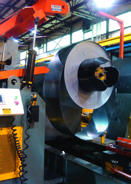
The back loop mode maintains a clock-spring loop beneath the coil as controlled loop storage for the feeder.
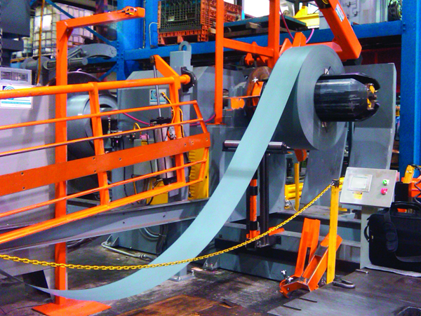
The forward loop mode maintains the loop between the reel and feed during an automatic coil run to allow processing light-gauge material at long feed lengths and at high stroke rates. A laser loop sensor controls the material payout during the automatic coil run.
The back loop mode provides the flexibility to process heavy-gauge materials by maintaining a clock-spring loop to form a free loop beneath the coil, as controlled loop storage for the feeder. The synchronized reel and feeder run at the same speed by replacing the brains and not the brawn.
The dual-function payout system also eliminates the sudden start-stop motions that induce wear and tear on the feeder, avoiding maintenance issues and costs while eliminating acceleration marks on the material.
Synchronized Plug-and-Play Systems
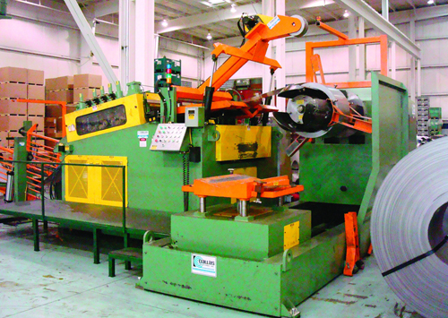
Can a conventional feed line, with old technology that has been in use for many years, be brought up to modern capabilities and standards? The following illustration demonstrates how it can be done. Consider a metalforming shop that, in 1985, purchased a new press and equipped it with an air feed—more than satisfactory at the time—as well as state-of-the-art back-end equipment. Fast forward to today, when, as many shops recently have concluded, an aging air feed fails to meet current needs. So, the shop invests in a new servo-drive unit that features the latest controls and electronics. All that’s needed is to synchronize the straightener and feeder.
Step one: Go to the back end and build a new platform to get an integrated system, in order to synchronize the straightener with the feeder. After 25 years of wear and tear, the brake on the reel must be rebuilt. Next, install an integration package that monitors brake pressure on the reel using a laser to measure coil OD. With this information, the control can adjust the speed rate or brake tension in conventional lines to avoid having material pulled too tightly or too loosely. As coil OD shrinks, the brake automatically adjusts, taking the operator out of the equation—no need to stop and make adjustments. As a result, the metalformer now has an integrated system that will perform to today’s standards, thanks to replacing the brains, not the brawn, via plug-and-play electronic upgrades.
The preceding scenario can potentially allow a shop to increase press capacity by 30 to 40 percent. In many cases, we’ve seen aging feed lines limit the performance of a fixed-speed press to running 36-in. stock at 27 strokes min. However, after upgrading as described above, the same press can run 56-in. parts at the same speed, without damaging the material. The operator need only stand by the press and collect parts. And, since the line is completely synchronized, all of the action occurs above ground, eliminating looping pits and their added expenses, maintenance and safety issues.
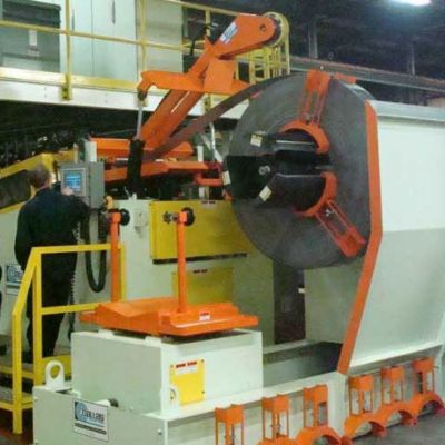
The back end of this line features laser loop control, coil-O.D. laser monitoring and a laser light pole for mode detection.
With all of these improvements made in the support equipment, the metalformer now can invest in variable-speed press controls to achieve even greater performance. The end result: Increased capacity and productivity and improved part quality, with existing equipment.
Controls Improve Efficiency, Quality
Current servo-feed controls use a trapezoidal feed motion, which results in quick, jerky motions that tend to cause slipping and induce strain on the die and material, and potentially damaging the part surface. During the past 40 years, several attempts have been made to develop a profile mode to allow press lines to obtain smoother feed motions, including use of mechanical and programmable cams. Other attempts to smooth feed motion featured the use of resolvers installed on presses, and servo-feed interfaces were developed to obtain integration and synchronization.
Now it is possible to operate in the profile mode using new electronic controls, without the need to install a resolver on the press. The key to the control system is its use of a selectable motion profile rather than a trapezoidal profile, to provide a smooth motion and material feed while utilizing the full press-feed window. Since the quick, jerky motions are eliminated, minimal stress is placed on the system’s mechanics and servo drive. This prevents die jams and material buckling while improving accuracy and reducing loop whip from payout equipment.
Based on the type of material, press and die being used, the operator can select from a choice of feed profiles that utilize the full feed window of the press. Once the press stroke rate, feed angle and profile type have been selected, the control system minimizes the stress transferred to the material, minimizing the potential for marking. MF
View Glossary of Metalforming Terms
See also: Dallas Industries
Technologies: Coil and Sheet Handling, Pressroom Automation
Comments
Must be logged in to post a comment. Sign in or Create an Account
There are no comments posted.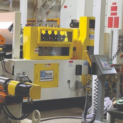 Coil and Sheet Handling
Dallas Industries Delivers Servo-Feed Line to Challenge Manu...
October 24, 2023
 Video
Video