 Generally, profound radius bends in sheet metal have required costly, specialized tooling, often antithetical to lean practices. Specialized large-radius tools can form only large radii and sit on a shelf until required for a job, tying up money and space. Step bending, also known as bump forming or incremental bending, cost effectively creates large bends with common off-the-shelf tooling. It also forms the basis for creating the transitional forms commonly used in the HVAC and food-and-beverage industries. Some forms are simple, such as an inline cone; others are more complex such as an offset square-to-round, or two intersecting round tubes. What these shapes have in common is the need to move a product from an opening in one plane to another. Fabricators can accomplish this by varying the radius pitch from one side of the step bend to the other, changing the achieved radii and shape.
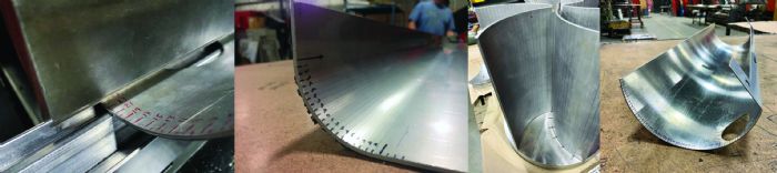 A step bend requires a series of small bends in proximity. The advantage is that this method does not require specialized tooling. The drawback, however, is that the outcome will not be a true radius, but rather a series of flat segments that render the final radius. These steps will be somewhat visible on the inner surface of the radius where the punch makes contact. The distance between these segments, known as radius pitch, and each bend angle will determine the smoothness of the finished radius. Surface-finish requirements dictate the choice of angle and pitch. A form with fewer bends will have a larger radius pitch and angle per bend, often leaving a choppy appearance. Forms that facilitate the liquid or powder flow during painting often need a very smooth surface and, as a result, will require more bends to accommodate that smoothness.
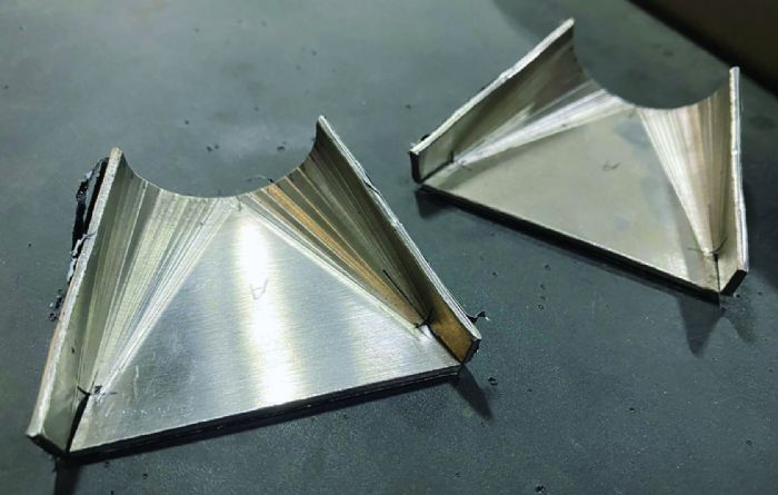
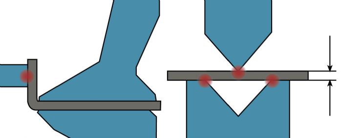 There are many ways to calculate a step bend, but the form’s requirements dictate the method chosen. To calculate the length of each bend segment:
Arc Length/Radius Pitch = Number of bends
Another formula often used: Total Degrees/Degrees per Bend = Number of Bends
Both formulas attack the job, but in different ways. Calculating by dividing the arc length by radius pitch often is used to ensure that the workpiece crosses the die opening; whereas, calculating based on the angle can guarantee a soft angle for each bend. For a smooth finish on most materials less than or equal to 12-gauge stainless steel, a 2-deg. bend or a radius pitch of 0.125 in. should suffice. Thick materials or extremely large radii will change these guidelines.
Folding or Press Brake Forming
A difficult bending challenge involves achieving the small-radius pitch required for a smooth finish. Sheet folders and press brakes can handle bumped radii, but they accomplish the task in different ways.
Folding machines clamp the workpiece in a stationary position, and a blade or wing bends the flange. This creates a bend between a fulcrum and a leverage point. With only two points of contact, the radius pitch can be as small as 0.001 in.
 On a press brake, the workpiece slides across three points of contact—the punch-nose radius, and the two shoulder radii of the die opening. The bend’s elongation occurs between the die’s shoulder radii—half in front of the punch’s contact point and half behind. The minimum-radius pitch must be half of the width of the die opening to bridge the gap. This creates a chopped appearance—certainly not an optimal method to achieve a smooth bend, but some simple workarounds can help.
Avoiding Choppiness
The first workaround option is to allow the workpiece’s previous bends to fall within the die opening. This can be tricky because the depth of penetration into the die is a moving target. The first bend is business as usual. Form, check, adjust and rehit if necessary. However, if the operator keeps the same depth of penetration on the second bend, the bend will fall short because the workpiece no longer lies flat across the die, creating uneven pressure. The third and all successive hits will follow this same pattern of falling further into the die and under-bending. This will require more depth corrections until the steps have fully traversed the die opening and begin to equalize (bridging the gap).
A second method to attain a smooth radius on the second and subsequent bends is to use a strip of urethane to take up the volume of the die, avoiding falling into the die entirely. The urethane removes the die width from the equation as the workpiece will be supported continually throughout the bending cycle. This reduces the minimum-radius pitch to 0.001 in., though the elongation still occurs on both sides of the punch. Notably, this method works well to 12-gauge thickness; with thicker work, the urethane takes a beating.
 A third approach is bending without a press brake. Folding often gets the call for step bending because the fulcrum keeps the part clamped and supported throughout the entire forming process. Reinserting an out-of-tolerance, step-bent part on a folder for rework is not really an option because of the clamping beams. But the concept can be applied when reworking a part slightly out of tolerance outside of a machine, be it a folder or a press brake. If the part is overbent, the operator need only clamp the part down to a worktable and hand-form it open. Working a part open is much easier than fighting to work the part to a more acute angle.
Dealing With Segments
Layout on a press brake is not as straightforward as it is on a folder. If the operator starts and ends bends using the bend allowance as the arc length, the radius will be too large. This occurs, in part, because in the brake, the material forms between three points of contact, with the punch being a pushing rod in the center. The elongation that occurs in front of the bend line will grow the radius beyond the anticipated start and end points. This overshoot will result in a longer arc length, manifesting in either an overbent angle or an enlarged radius.
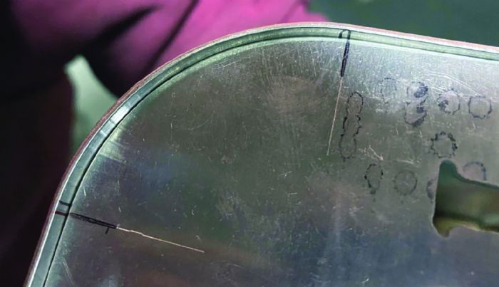
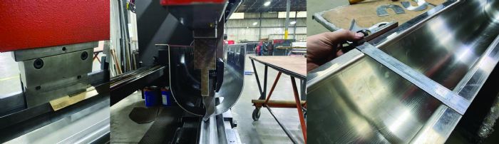
This leads to another variable that affects press brakes and folders—segments. Using a gauge cut to the inside radius reveals areas of the bend that may be too tight or loose. A truly smooth radius will match an inside template perfectly. However, a segment will prevent the radius of an inside template from reaching its correct depth. The larger the segments, the more the interference.
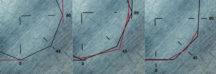
 Often, operators account for the elongation overshoot and segment interference by cheating the angle of the start and end points. Making these two outermost bends at half of the angle of the interior bends may work reasonably well but produces a slightly parabolic shape. Moving the start and end points of the arc length inward by half of the radius pitch renders a better result. This will rotate the interference point of the segments to the desired start and end of the bend’s arc.
Bumping the U
Preventing canoeing is essential to achieving a straight, post-formed part. Step bending tends to magnify errors. A 0.5-deg. difference per bend will accumulate to a 5-deg. difference after performing only 10 bends. However, this may break stride with lean manufacturing rules; using test strips from the drop of the sheet will help ease any sheet-to-sheet variance. Eliminating variability is necessary for a step bend. To do this, the operator performs a 90-deg. bend and checks squareness at multiple locations along the test piece. This provides the opportunity to make adjustments, with global crowning and localized shimming on the same material as the workpiece. Normal tolerance for sheet metal allows for more variation at the edges of the sheet compared to the center of the sheet. Therefore, the test material should be cut away from the sheet edge when possible.
Once the machine has been set up and adjusted, the operator forms the outer flanges and begins work on the U section. If the operator forms the U section from the center outward, the part will crash into the ram before completing all of the bends. Forming from the edges toward the center will ensure clearance between the workpiece and the machine. Care must be taken to verify that the radius is correct near the outer edges before moving toward the center. There will be no option to rehit these bends if the hits are too light.
Often, the operator gauges the workpiece by eye, aligning bend lines with a reference point. This can be anything stationary such as the punch nose, the die-shoulder radius, a marker line on the urethane or even a square blade set off the front of the die. This requires great operator skill to move the part by hand to an exacting dimension. They will form a few bends, then check the radius of the workpiece against a template. If the radius is too large, the operator adjusts the machine and rehits the workpiece until it falls within specification. If the radius is too small, the operator will need to either hand-work the part open or flip the part over and use a press to unbend the part slightly.
In trying to fix an inconsistent radius by hand, pulling open will lighten and pushing over will tighten, but where the part is held determines which area of the radius changes. Clamping the part down to a worktable, similar to how a folder works, will force the change to occur at a leverage point. Note: This radius manipulation also will affect the finished flange lengths.
All of this may lead to more questions:
- What is the minimum punch-nose radius?
- How close must the bends be?
- What size is the lower die opening?
- Should I bridge the gap?
- Is urethane required?
The answer: That depends.
Step Bending Offers Options
Step bending is not limited to small-radius tooling. Operators also can use large-radius tools to create smooth forms in fewer steps than a small-radius tool. The smaller the punch radius, the closer the steps must be for a smooth finish. A too-small-radius punch-nose will penetrate the material and make the steps more visually pronounced.
Bridging the die width often results in a choppy finish. It is possible to choose a smaller-than-usual die opening for step bending because of the reduced penetration into the die space—though tonnage limits still must be observed. Falling within the die opening will produce a smoother finish but urethane is the preferred method because it reduces the radius-pitch requirements, eases gauging, and renders a mar-free finish.
Despite sharing the press brake operator title, many operators find that the types of jobs they form are completely different. An operator bumping thick high-tensile-strength AR400 for a construction vehicle has a much different perspective than one bumping 20-gauge, mirror-polished architectural columns. The rules of thumb differ for each, and the tribal knowledge being passed down from generation to generation may work only in the environment for which it was created. The best experience is hands-on. Fabricators should grab a piece of test material and step into the future. MF
Justin Talianek is lead press brake operator for Keystone Fabricating, Bethlehem, PA, 610/868-0900.
View Glossary of Metalforming Terms
Technologies: Bending