
Page 43 - MetalForming August 2019
P. 43
The Science of Forming
Variation in Gauge Thickness
Uncoated Steel
Galvanized Steel
Stainless Steel
Aluminum, Brass and Copper
in.
mm
in.
mm
in.
mm
in.
mm
16-Gauge Sheet
0.0598
1.519
0.0635
1.613
0.0625
1.588
0.0508
1.290
Gauge-thickness definition varies with sheet metal—as does tolerance.
that falls into defined ranges of tensile properties as well as chemistry. Similar challenges are seen with other sheet metal types.
Thickness Tolerance and Cutting Clearance
Measure the sheet metal blank thickness before conducting the first tryout hits. Do not rely on the metal certs for thickness—the document shows only the minimum or nominal thickness, and does not represent the coil on your shop floor. If blanking, trimming or cutting clearance is deter- mined as a percentage of thickness, realize that these percentages change depending on the choice of actual, minimum or nominal thickness as your reference.
The way you specify sheet thickness influences the product received. When ordering by gauge number, know that the numerical gauge designation denotes a different thickness depend- ing on the metal described, as well as if the metal exists in sheet or wire form, or if it’s been hot or cold rolled (see Variation in Gauge Thickness table). Also changing: the allowable thickness tolerance, which could reach ±10 per- cent of the nominal value.
As an example, when ordering 16- gauge galvanized steel sheet, the sheet metal received may exhibit thickness anywhere from 0.0575 to 0.0695 in. If your goal is to set cutting clearance to 10 percent of metal thickness, cut- edge performance will change signif- icantly depending on your use of nom- inal, minimum or maximum thickness as a reference, and on where any given shipment falls within the allowable
spectrum of metal thickness.
If cut edges influence your ability to produce quality stampings, order sheet metal to an appropriate thickness tolerance and measure each shipment. Are there topics you’d like to see covered in future Science of Forming columns? Let me know at ScienceOf- Forming@EQSgroup.com. MF
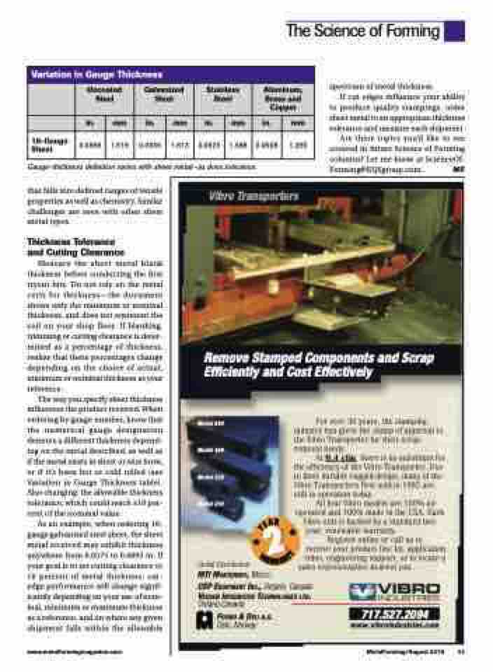
Vibro Transporters
Remove Stamped Components and Scrap Efficiently and Cost Effectively
Model 850
Model 450
Model 320
Model 250
Global Distribution
For over 30 years, the stamping industry has given the stamp of approval to the Vibro Transporter for their scrap removal needs.
At 0.4 cfm, there is no substitute for the efficiency of the Vibro Transporter. Due to their durable rugged design, many of the Vibro Transporters first sold in 1985 are still in operation today.
All four Vibro models are 100% air operated and 100% made in the USA. Each
Vibro unit is backed by a standard two- year, renewable warranty.
Register online or call us to receive your product line kit, application video, engineering support, or to locate a
sales representative nearest you.
MTI MONTERREY, MEXICO
CSP EQUIPMENT INC., Ontario, Canada
VEUGEN INTEGRATED TECHNOLOGIES LTD.
Ontario,Canada
FOSMO & DELI A.S.
Oslo, Norway
717.527.2094
www.vibroindustries.com
www.metalformingmagazine.com
MetalForming/August 2019 41
A
E
R
Y
2
Y
T
N
A
R
W
A
R
