
Page 44 - MetalForming-Aug-2018-issue
P. 44
Welding Well
By Tom Snow
Resistance-Welding Machines Are Thirsty...
And What to Do About It
Long known as water hogs, resist- ance-welding (RW) machines, including spot, projection, seam, butt and flash welders, generate heat due to the high secondary-welding amperages used.
Therefore, with an RW machine run- ning at high speed, an adequate flow of cooling water is one of the most important variables of the resistance- welding process. The typical machine requires 1 to 3 gal./min. per cooling circuit, and sometimes more.
The standard AC resistance welders used for decades by metalformers can tolerate some overheating, but the newer medium-frequency direct-cur- rent (MFDC) inverter-power supplies, more commonly used today, are prone to failure due to inadequate water flow.
Often, the required total water flow required is substantial due to several parallel water circuits per machine. For example, the water-cooling needs of specially designed automated multi- gun resistance welders with multiple transformers and tips easily can total water flows of 10 to 20 gal./min.
In the past, manufacturers often connected RW machines to their incoming municipal water supply with- out giving it another thought. However, the days of cheap and plentiful city water are long gone, and additional
TomSnowisCEOofT.J. Snow Co., Chattanooga, TN, a supplier of resist- ance-welding machines, supplies, service and training. Snow, the imme- diate past chairman of the Resistance Welding Manufacturing Alliance, a standing committee of the American Welding
Society, shares his resistance-welding insights in MetalForming magazine’s Welding Well column every-other month.
Tom Snow, CEO
T. J. Snow Co. tomsnow@tjsnow.com
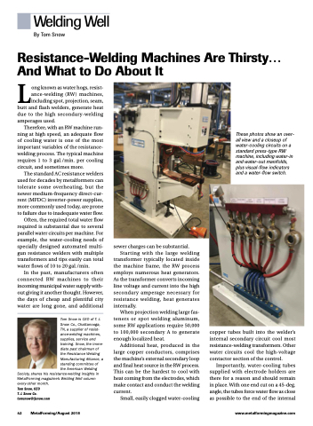
These photos show an over- all view and a closeup of water-cooling circuits on a standard press-type RW machine, including water-in and water-out manifolds, plus visual-flow indicators and a water-flow switch.
sewer charges can be substantial. Starting with the large welding transformer typically located inside the machine frame, the RW process employs numerous heat generators. As the transformer converts incoming line voltage and current into the high secondary amperage necessary for resistance welding, heat generates
internally.
When projection welding large fas-
teners or spot welding aluminum, some RW applications require 50,000 to 100,000 secondary A to generate enough localized heat.
Additional heat, produced in the large copper conductors, comprises the machine’s external secondary loop and final heat source in the RW process. This can be the hardest to cool with heat coming from the electrodes, which make contact and conduct the welding current.
Small, easily clogged water-cooling
copper tubes built into the welder’s internal secondary circuit cool most resistance-welding transformers. Other water circuits cool the high-voltage contactor section of the control.
Importantly, water-cooling tubes supplied with electrode holders are there for a reason and should remain in place. With one end cut on a 45-deg. angle, the tubes force water flow as close as possible to the end of the internal
42 MetalForming/August 2018
www.metalformingmagazine.com
