
Page 41 - MetalForming-Jul-2018-issue
P. 41
Shaving and Burnishing Guidelines
While generally associated with burnished openings such as holes, many candidates exist for shaving, including free-edge features, burnished edges and die-cut features requiring close tolerances.
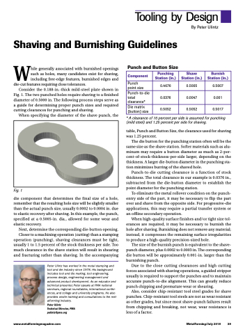
Consider the 0.188-in.-thick mild-steel plate shown in Fig. 1. The two punched holes require shaving to a finished diameter of 0.5000 in. The following process steps serve as a guide for determining proper punch sizes and required cutting clearances for punching and shaving.
When specifying the diameter of the shave punch, the
Punch and Button Size
Tooling by Design
By Peter Ulintz
Component
Punching Station (in.)
Shave Station (in.)
Burnish Station (in.)
Punch point size
0.4676
0.5005
0.5007
Punch-to-die total clearance*
0.0376
0.0047
0.001
Die matrix (button) size
0.5052
0.5052
0.5017
Fig. 1
die component that determines the final size of a hole, remember that the resulting hole size will be slightly smaller than the actual punch size, usually 0.0002 to 0.0004 in. due to elastic recovery after shaving. In this example, the punch, specified at a 0.5005-in. dia., allowed for some wear and elastic recovery.
Next, determine the corresponding die-button opening.
Closer to a machining operation (cutting) than a stamping operation (punching), shaving clearances must be tight, usually 1 to 1.5 percent of the stock thickness per side. Too much clearance in the shave station will result in shearing and fracturing rather than shaving. In the accompanying
Peter Ulintz has worked in the metal stamping and tool and die industry since 1978. His background includes tool and die making, tool engineering, process design, engineering management and advanced product development. As an educator and technical presenter, Peter speaks at PMA national seminars, regional roundtables, international confer- ences, and college and university programs. He also provides onsite training and consultations to the met- alforming industry.
Peter Ulintz
Technical Director, PMA pulintz@pma.org
* A clearance of 10 percent per side is assumed for punching (mild steel) and 1.25 percent per side for shaving.
table, Punch and Button Size, the clearance used for shaving was 1.25 percent.
The die button for the punching station often will be the same size as the shave station. Softer materials such as alu- minum may require a button diameter as much as 2-per- cent-of-stock-thickness-per-side larger, depending on the thickness. A larger die-button diameter in the punching sta- tion minimizes burring of the shaved hole.
Punch-to-die cutting clearance is a function of stock thickness. The total clearance in our example is 0.0376 in., subtracted from the die-button diameter to establish the point diameter for the punching station.
To eliminate the metal rollover condition on the punch- entry side of the part, it may be necessary to flip the part over and shave from the opposite side. For progressive-die applications, this may require a partial transfer system or an offline secondary operation.
When high-quality surface finishes and/or tight size tol- erances are required, it may be necessary to burnish the hole after shaving. Burnishing does not remove any material; instead, it compresses the remaining surface irregularities to produce a high-quality precision-sized hole.
The size of the burnish punch is equivalent to the shave- punch diameter, plus 0.0002 to 0.0003 in. The corresponding die button will be approximately 0.001-in. larger than the burnishing punch.
Due to the close cutting clearances and high cutting forces associated with shaving operations, a guided stripper usually is required to support the punches and to maintain accurate punch-to-die alignment. This can greatly reduce punch chipping and premature wear or shearing.
Also, consider chip-resistant tool steel grades for shave punches. Chip-resistant tool steels are not as wear resistant as other grades, but since most shave-punch failures result from chipping and breaking, not wear, wear resistance is less of a factor.
www.metalformingmagazine.com
MetalForming/July 2018 39
