
Page 46 - MetalForming-Apr-2018-issue
P. 46
Welding Well
By Tom Snow
Resistance Welding Fasteners to High-Strength Steels
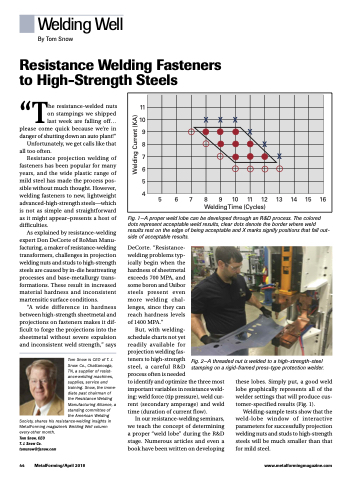
11 10 9 8 7 6 5 4
5 6 7 8 9 10 11 12 13 14 15 16 WeldingTime (Cycles)
XXX
X
X
X
“The resistance-welded nuts on stampings we shipped last week are falling off... please come quick because we’re in danger of shutting down an auto plant!” Unfortunately, we get calls like that
all too often.
Resistance projection welding of
fasteners has been popular for many years, and the wide plastic range of mild steel has made the process pos- sible without much thought. However, welding fasteners to new, lightweight advanced-high-strength steels—which is not as simple and straightforward as it might appear–presents a host of difficulties.
As explained by resistance-welding expert Don DeCorte of RoMan Manu- facturing, a maker of resistance-welding transformers, challenges in projection welding nuts and studs to high-strength steels are caused by in-die heattreating processes and base-metallurgy trans- formations. These result in increased material hardness and inconsistent martensitic surface conditions.
“A wide difference in hardness between high-strength sheetmetal and projections on fasteners makes it dif- ficult to forge the projections into the sheetmetal without severe expulsion and inconsistent weld strength,” says
TomSnowisCEOofT.J. Snow Co., Chattanooga, TN, a supplier of resist- ance-welding machines, supplies, service and training. Snow, the imme- diate past chairman of the Resistance Welding Manufacturing Alliance, a standing committee of the American Welding
Society, shares his resistance-welding insights in MetalForming magazine’s Welding Well column every-other month.
Tom Snow, CEO
T. J. Snow Co. tomsnow@tjsnow.com
Fig. 1—A proper weld lobe can be developed through an R&D process. The colored dots represent acceptable weld results, clear dots denote the border where weld results rest on the edge of being acceptable and X marks signify positions that fall out- side of acceptable results.
DeCorte. “Resistance- welding problems typ- ically begin when the hardness of sheetmetal exceeds 700 MPA, and some boron and Usibor steels present even more welding chal- lenges, since they can reach hardness levels of 1400 MPA.”
But, with welding-
schedule charts not yet
readily available for
projection welding fas-
teners to high-strength
steel, a careful R&D
process often is needed
to identify and optimize the three most important variables in resistance weld- ing: weld force (tip pressure), weld cur- rent (secondary amperage) and weld time (duration of current flow).
In our resistance-welding seminars, we teach the concept of determining a proper “weld lobe” during the R&D stage. Numerous articles and even a book have been written on developing
44 MetalForming/April 2018
www.metalformingmagazine.com
Fig. 2—A threaded nut is welded to a high-strength-steel stamping on a rigid-framed press-type protection welder.
these lobes. Simply put, a good weld lobe graphically represents all of the welder settings that will produce cus- tomer-specified results (Fig. 1).
Welding-sample tests show that the weld-lobe window of interactive parameters for successfully projection welding nuts and studs to high-strength steels will be much smaller than that for mild steel.
Welding Current (KA)
