
Page 88 - MetalForming July 2017
P. 88
Tooling by Design
By Peter Ulintz
Blank-and-Draw-Process Problems–Part Two
In my May 2017 column, I addressed a question submitted by a reader regarding press-tonnage calculations.
“On several occasions we had to move our dies to a larger press because the press we selected did not have enough power,” the reader comment- ed. “In fact, the press slowed down noticeably during production. When we moved the die to a larger-tonnage press, the problem went away.”
The reader’s concern was that the engineers were using incorrect formu- las for calculating the required press forces. As it turned out, the force cal- culations used did not include the force required to counteract the draw-pad forces, nor was the reduction in avail- able working force (de-rated tonnage) considered as the distance increased above the bottom of the press stroke. Still, the calculations were close enough to get the job assigned to a press with adequate tonnage capacity. Why, then, did the reader experience problems (i.e., press slowing down) running this particular job? And more importantly, why did the problem disappear when the die was moved to a press with a greater tonnage capacity?
First, it is important to recognize
Peter Ulintz has worked in the metal stamping and tool and die industry since 1978. His back- ground includes tool and die making, tool engi- neering, process design, engineering manage- ment and advanced product development. As an educator and technical
presenter, Peter speaks at PMA national seminars, regional roundtables, international conferences, and college and university programs. He also pro- vides onsite training and consultations to the met- alforming industry.
Peter Ulintz
Technical Director, PMA pulintz@pma.org
the difference
between press ton-
nage and press ener-
gy. The tonnage rat-
ing of a press is the
maximum load that
can be exerted in
continuous opera-
tion without causing
damage to the machine structure or its drive system. On the other hand, the energy rating of a press is the prod- uct of an applied press load and the distance through which the load must be applied. Since energy is expended with each stroke of the press—and this energy must come from somewhere— we must direct our attention to the main drive motor, the flywheel and geartrain.
The main motor is the only source of energy for the stamping press, and it must have sufficient horsepower to sup- ply the demands of the entire stamping operation. The press flywheel, by virtue of its mass and rotational speed, serves as the energy-storage device. The energy stored in the flywheel often is expressed as in.-tons of torque. In combination, the flywheel stores and delivers the required work energy while the electrical motor restores depleted energy by main- taining flywheel speed and avoiding excessive slowdown.
Deep-drawing operations consume large amounts of press energy due to their long working distances, some- times beginning several inches above the bottom of the press stroke. For example, pushing 50 tons through 1 in. of drawing requires approximately 50 in.-tons of energy, but pushing 50 tons through 3 in. of drawing requires approximately 150 in.-tons.
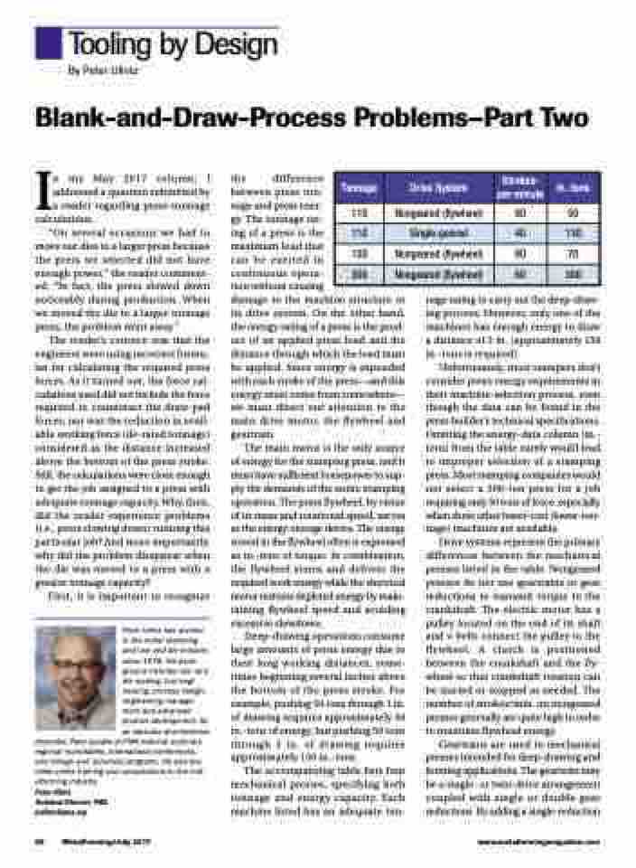
The accompanying table lists four mechanical presses, specifying both tonnage and energy capacity. Each machine listed has an adequate ton-
nage rating to carry out the deep-draw- ing process. However, only one of the machines has enough energy to draw a distance of 3 in. (approximately 150 in.-tons is required).
Unfortunately, most stampers don’t consider press-energy requirements in their machine-selection process, even though the data can be found in the press builder’s technical specifications. Omitting the energy-data column (in.- tons) from the table surely would lead to improper selection of a stamping press. Most stamping companies would not select a 300-ton press for a job requiring only 50 tons of force, especially when three other lower-cost (lower-ton- nage) machines are available.
Drive systems represent the primary differences between the mechanical presses listed in the table. Nongeared presses do not use geartrains or gear reductions to transmit torque to the crankshaft. The electric motor has a pulley located on the end of its shaft and v-belts connect the pulley to the flywheel. A clutch is positioned between the crankshaft and the fly- wheel so that crankshaft rotation can be started or stopped as needed. The number of strokes/min. on nongeared presses generally are quite high in order to maintain flywheel energy.
Geartrains are used in mechanical presses intended for deep-drawing and forming applications. The geartrain may be a single- or twin-drive arrangement coupled with single or double gear reductions. By adding a single-reduction
Tonnage
Drive System
Strokes- per-minute
In.-tons
110
Nongeared (flywheel)
80
50
110
Single-geared
40
130
150
Nongeared (flywheel)
80
70
300
Nongeared (flywheel)
60
300
86 MetalForming/July 2017
www.metalformingmagazine.com
