
Page 96 - MetalForming October 2016
P. 96
The Science of Forming
By Stuart Keeler
Some Forming Problems Have No Solutions
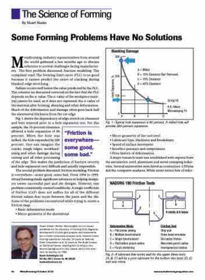
Blanking Damage
300
200
100
0
ABCD
A = Milled
B = 10% Clearance Burr Removed
C = 10% Clearance
D = 40% Clearance
30 Ksi YS
R.R. Hilson Microalloying 75
Metalforming-industry representatives from around the world gathered a few months ago to discuss solutions to several challenges facing manufactur- ers. The first problem discussed: fracture modeling. The complaint read: The forming-limit curve (FLC) is no good because it cannot predict the onset of cracking during blanked-edge stretching.
Failure occurs well below the value predicted by the FLC. The solution we discussed centered on the fact that the FLC depends on the n-value. The n-value of the workpiece mate- rial cannot be used, as it does not represent the n-value of the material after forming, shearing and other deformation. Much of the deformation and damage often goes back half the sheetmetal thickness from the cut edge.
Fig. 1 shows the dependency of edge stretch on clearance and burr removal prior to a hole-expansion test. For this sample, the 10-percent clearance
allowed a hole expansion of 80
percent. When the hole was
milled, the hole expanded by 280
percent. One can imagine the
cracks, rough edges, workhard-
ening and other damage during
cutting and all other processing
of the edge. This makes the prediction of fracture severity and hole expansion very difficult and usually impossible.
The second problem discussed: friction modeling. Friction is everywhere—some good, some bad. From 1994 to 1999, virtual forming made significant advances in helping design- ers create successful part and die designs. However, one problem consistently created roadblocks: A single coefficient of friction (CoF) does not suffice for all of the different friction values that occur between the parts and the die. Some of the problems encountered while trying to create a friction map:
• Basic deformation mode
• Micro-geometry of the sheetmetal
Stuart Keeler (Keeler Technologies LLC) is known worldwide for his discovery of forming limit diagrams, development of circle-grid analysis and implementa- tion of other press-shop analysis tools. Keeler’s metal- forming experience includes 24 years at National Steel Corporation and 12 years at The Budd Compa- ny Technical Center, enabling him to bring a very diverse background to this column and to the semi- nars he teaches for PMA.
Keeler Technologies LLC
P.O. Box 283 | Grosse Ile, MI 48138 keeltech@comcast.net
Fig. 1—Typical hole expansion is 80 percent. A milled hole will provide 280-percent expansion.
• Micro-geometry of the tool steel
• Lubricant type, thickness and breakdown
• Speed of surface movement
• Interface pressure and temperature
• Prior history of deformation.
A major research team was established with experts from
the automotive, steel, aluminum and metal-stamping indus- tries. Several universities were hired as contractors. LSDyna did the computer analyses. While some minor bits of infor-
“Friction is everywhere— some good, some bad.”
NADDRG 180 Friction Tests
Deformation Mode
A = Flat binder sliding
B = Multiple bend/unbend
C = Single bend/unbend
D = Flat bottom punch radius E = Punch stretching
B
6 steels & 6 lubes
Friction Test
Strip pull
Draw-bead simulator Die radius friction Marciniak punch radius Hemispherical rotation
CC
D
E
A
94
MetalForming/October 2016
www.metalformingmagazine.com
Fig. 2—A lubricant that works well for the upper three tests
(A, B, C) will be a poor lubricant for the bottom two tests (D, E) and vice-versa.
Hole Expansion, %
