
Page 78 - MetalForming October 2016
P. 78
The Onus is on Die Designers
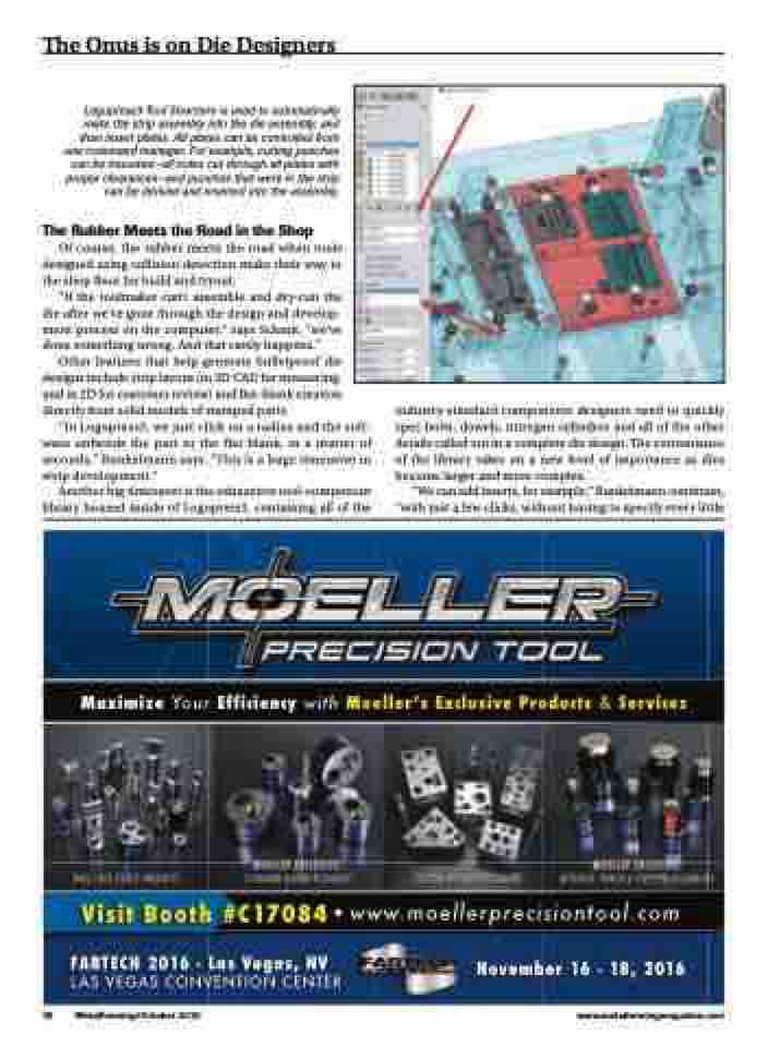
Logopress3 Tool Structure is used to automatically
mate the strip assembly into the die assembly, and then insert plates. All plates can be controlled from one command manager. For example, cutting punches can be mounted—all holes cut through all plates with proper clearances—and punches that were in the strip can be derived and inserted into the assembly.
The Rubber Meets the Road in the Shop
Of course, the rubber meets the road when tools designed using collision detection make their way to the shop floor for build and tryout.
“If the toolmaker can’t assemble and dry-run the die after we’ve gone through the design and develop- ment process on the computer,” says Schmit, “we’ve done something wrong. And that rarely happens.”
Other features that help generate bulletproof die designs include strip layout (in 3D CAD for measuring, and in 2D for customer review) and flat-blank creation directly from solid models of stamped parts.
“In Logopress3, we just click on a radius and the soft- ware unbends the part to the flat blank, in a matter of seconds,” Bunkelmann says. “This is a huge timesaver in strip development.”
Another big timesaver is the exhaustive tool-component library housed inside of Logopress3, containing all of the
industry-standard components designers need to quickly spec bolts, dowels, nitrogen cylinders and all of the other details called out in a complete die design. The convenience of the library takes on a new level of importance as dies become larger and more complex.
“We can add inserts, for example,” Bunkelmann continues, “with just a few clicks, without having to specify every little
�������� ���� ���������� ���� ��������� ��������� �������� � ��������
����� ����� ������� � ����������������������������
������� ���� � ��� ������ ��
��� ����� ���������� ������
�������� �� � ��� ����
76
MetalForming/October 2016 www.metalformingmagazine.com
