
Page 38 - MetalForming December 2015
P. 38
The Science of Forming By Stuart Keeler
Cutting Can Spoil Stretchability
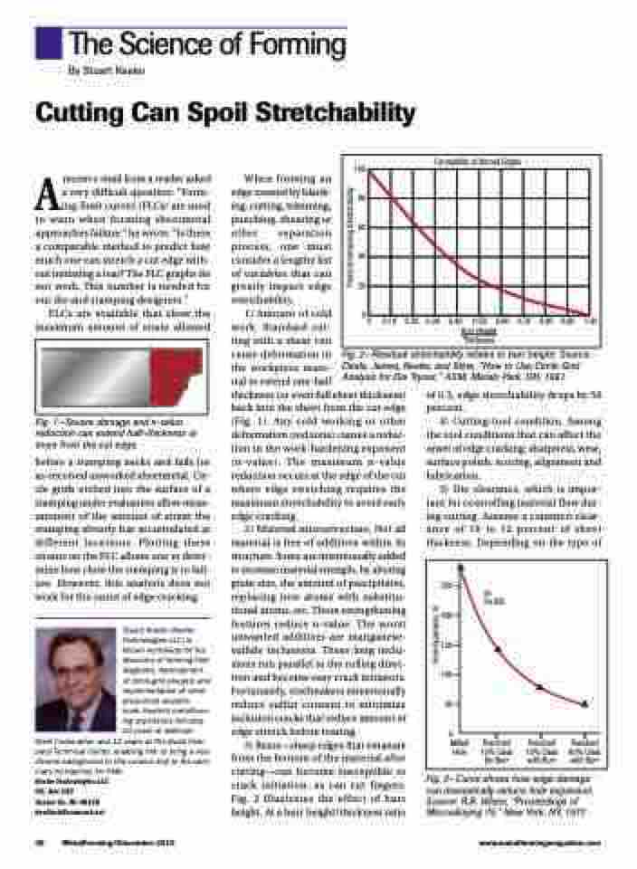
100 80 60 40 20 0
Formability of Burred Edges
0 0.10 0.20 0.30 0.40 0.50 0.60 0.70 0.80 0.90 1.00
Burr Height
Thickness
Arecent e-mail from a reader asked a very difficult question: “Form- ing-limit curves (FLCs) are used to warn when forming sheetmetal approaches failure,” he wrote. “Is there a comparable method to predict how much one can stretch a cut edge with- out initiating a tear? The FLC graphs do not work. This number is needed for our die and stamping designers.”
FLCs are available that show the maximum amount of strain allowed
Fig. 1—Severe damage and n-value reduction can extend half-thickness or more from the cut edge.
before a stamping necks and fails for as-received unworked sheetmetal. Cir- cle grids etched into the surface of a stamping under evaluation allow meas- urement of the amount of strain the stamping already has accumulated at different locations. Plotting these strains on the FLC allows one to deter- mine how close the stamping is to fail- ure. However, this analysis does not work for the onset of edge cracking.
Stuart Keeler (Keeler Technologies LLC) is known worldwide for his discovery of forming limit diagrams, development of circle-grid analysis and implementation of other press-shop analysis
tools. Keeler’s metalform- ing experience includes 24 years at National
Steel Corporation and 12 years at The Budd Com- pany Technical Center, enabling him to bring a very diverse background to this column and to the sem- inars he teaches for PMA.
Keeler Technologies LLC P.O. Box 283
Grosse Ile, MI 48138 keeltech@comcast.net
When forming an edge created by blank- ing, cutting, trimming, punching, shearing or other separation process, one must consider a lengthy list of variables that can greatly impact edge stretchability.
1) Amount of cold
work. Standard cut-
ting with a shear can
cause deformation in Fig. 2—Residual stretchability relates to burr height. Source:
the workpiece mate- Dinda, James, Keeler, and Stine, “How to Use Circle Grid rial to extend one-half Analysis for Die Tryout,” ASM, Metals Park, OH, 1981.
thickness (or even full sheet thickness) back into the sheet from the cut edge (Fig. 1). Any cold working or other deformation (red zone) causes a reduc- tion in the work-hardening exponent (n-value). The maximum n-value reduction occurs at the edge of the cut where edge stretching requires the maximum stretchability to avoid early edge cracking.
2) Material microstructure. Not all material is free of additives within its structure. Some are intentionally added to increase material strength, by altering grain size, the amount of precipitates, replacing iron atoms with substitu- tional atoms, etc. These strengthening features reduce n-value. The worst unwanted additives are manganese- sulfide inclusions. These long inclu- sions run parallel to the rolling direc- tion and become easy crack initiators. Fortunately, steelmakers intentionally reduce sulfur content to minimize inclusion cracks that reduce amount of edge stretch before tearing.
3) Burrs—sharp edges that emanate from the bottom of the material after cutting—can become susceptible to crack initiation, as can cut fingers. Fig. 2 illustrates the effect of burr height. At a burr height/thickness ratio
of 0.3, edge stretchability drops by 50 percent.
4) Cutting-tool condition. Among the tool conditions that can affect the onset of edge cracking: sharpness, wear, surface polish, scoring, alignment and lubrication.
5) Die clearance, which is impor- tant for controlling material flow dur- ing cutting. Assume a common clear- ance of 10 to 12 percent of sheet thickness. Depending on the type of
250
ys
200 150 100
50
0 Milled
Hole
Punched 10% Clear No Burr
Punched 10% Clear with Burr
Punched 40% Clear with Burr
30 KSI
36 MetalForming/December 2015
www.metalformingmagazine.com
Fig. 3—Curve shows how edge damage can dramatically reduce hole expansion. Source: R.R. Hilsen, “Proceedings of Microalloying 75,” New York, NY, 1977.
Hole Expansion, %
Percent remaining Stretchability
