
Page 49 - MetalForming September 2014
P. 49
When You Need it Fast
���� ����� � ����� �����
��� ������ ����� � ������ ����� ��� �����������TM �����������TM � ���������� ��������
In-Stock Items Ship in 24-48 Hours
Call us at
1-800-543-1566
www.diehlsteel.com
See us at
AMTS 2014 – Booth 610 FABTECH 2014 – Booth B1351
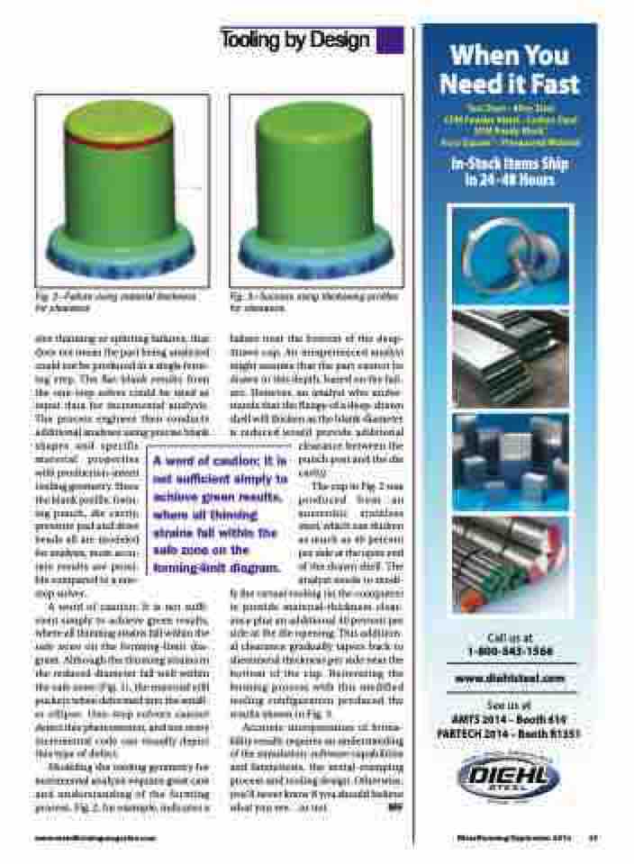
Fig. 2—Failure using material thickness for clearance
sive thinning or splitting failures, that does not mean the part being analyzed could not be produced in a single form- ing step. The flat-blank results from the one-step solver could be used as input data for incremental analysis. The process engineer then conducts additional analyses using precise blank shapes and specific
Fig. 3—Success using thickening profiles for clearance
failure near the bottom of the deep- drawn cup. An inexperienced analyst might assume that the part cannot be drawn to this depth, based on the fail- ure. However, an analyst who under- stands that the flange of a deep-drawn shell will thicken as the blank diameter is reduced would provide additional
material properties with production-intent tooling geometry. Since the blank profile, form- ing punch, die cavity, pressure pad and draw beads all are modeled for analysis, more accu- rate results are possi- ble compared to a one- step solver.
A word of caution: It is not sufficient simply to achieve green results, where all thinning strains fall within the safe zone on the forming-limit diagram.
clearance between the punch post and the die cavity.
The cup in Fig. 2 was produced from an austenitic stainless steel, which can thicken as much as 40 percent per side at the open end of the drawn shell. The analyst needs to modi-
A word of caution: It is not suffi- cient simply to achieve green results, where all thinning strains fall within the safe zone on the forming-limit dia- gram. Although the thinning strains in the reduced diameter fall well within the safe zone (Fig. 1), the material still puckers when deformed into the small- er ellipse. One-step solvers cannot detect this phenomenon, and not every incremental code can visually depict this type of defect.
Modeling the tooling geometry for incremental analysis requires great care and understanding of the forming process. Fig. 2, for example, indicates a
fy the virtual tooling (in the computer) to provide material-thickness clear- ance plus an additional 40 percent per side at the die opening. This addition- al clearance gradually tapers back to sheetmetal thickness per side near the bottom of the cup. Reiterating the forming process with this modified tooling configuration produced the results shown in Fig. 3.
Accurate interpretation of forma- bility results requires an understanding of the simulation-software capabilities and limitations, the metal-stamping process and tooling design. Otherwise, you’ll never know if you should believe what you see...or not. MF
www.metalformingmagazine.com
MetalForming/September 2014 47
Tooling by Design
