
Page 30 - MetalForming August 2014
P. 30
Machining and forming process- es, as well as heattreating on large shafts used in the oil, marine, aerospace and automotive industries, can cause workpieces to warp. Hydraulic straightening presses provide tight control for straightening, resulting in accurate, well-functioning parts and substantial cost savings. In some cases, straightening is the only way to condition or prepare the mate- rial in order to machine the component appropriately. The same is true for straightening of plates.
Hydraulic straightening presses also often get the call for straightening large weldments and plates, as well as shafts. Large weldments can become deformed or warped from heat from the welding process; often these weldments must be straightened prior to continuing on with secondary production processes.
Tom Lavoie is applications engineer- ing manager, Greenerd Press & Machine Co., Inc., Nashua, NH: 603/889-4101, www.greenerd.com.
Shaft work, a little more complicat- ed, can come in many sizes. Large- diameter shafts, defined as several inches in diameter or larger, are diffi- cult to automate into a process for straightening.
The Right Press Design for the Job
Fabricators select from two types of press designs for straightening— moving-gantry or fixed-head. Plate and weldment applications typically require a moving-gantry press that moves the head over the work front-to-back or left-to-right, regardless of where it is located on the press bed. A shaft- straightening press has only one axis of travel, located on-center with the shaft.
When straightening large drive shafts and pipes such as those used in oilfield applications, which can be dif- ficult to manipulate, fabricators typi- cally opt for a press that can locate over the high spot (bend in the shaft) and apply tonnage to straighten the shaft within acceptable tolerances.
Straight Talk on
Hydraulic
Straightening-
Press Applications
BY TOM LAVOIE
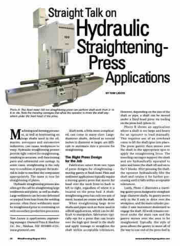
Photo A: This fixed-head 100-ton straightening press can perform shaft work from 2- to 8-in. dia. Note the traveling carriages that allow the operator to move the shaft any- where under the fixed head of the press.
However, depending on the size of the shaft or pipe, a shaft can be moved under a fixed-head press via tooling on the press bed (photo A).
Photo B shows an application where a shaft is too large and heavy for an operator to load manually. This requires use of an overhead crane to lift the shaft/gear into place. The press gantry then moves over the shaft to the appropriate spot to apply the straightening force. The traveling carriages support the shaft and are hydraulically operated to raise and lower the shaft off and on to the V-blocks. After pressing the shaft, the operator hydraulically lifts the shaft and rotates it for further pro- cessing until it falls within acceptable tolerances.
Lastly, Photo C illustrates a travel- ing-gantry press designed to straighten large-diameter shafts. Its gantry moves only in the X axis to drive over the workpiece, and the main cylinder pro- vides Z-axis movement downward to engage the shaft. All work remains cen- tered under the main ram and the gantry moves over the area to be straightened. Typically, this style of press allows the gantry to move all of the way to one end of the press bed in
28 MetalForming/August 2014
www.metalformingmagazine.com
