
Page 36 - MetalForming July 2014
P. 36
Customer Responsiveness Defined
������� �������� ��� ����� � ������
����� ����� ������ ��� ��������
�������� �� ������ ��� ����� ��������
���� ����� ����� ��������
����� ����� ���������� �������� ���� ���������� �������
������������� ����� ��������
������ ���� ���������� �������� ����������
����� ����� ������ � ��������
������ ����� �������� ������ ��� �������
��������� ���� �������
���� � ���� ��������� ��������
����� ������� � ���� ����������
���� �� ��� ���
������������ ������������������������������ ����������������������������
34 MetalForming/July 2014
www.metalformingmagazine.com
specified for this latest job proved particularly challenging. They’re not your standard rivet, and instead are stubby—nearly equal in length and head diameter (7⁄16 in.).
“That makes the rivets difficult to control when feeding them through a round tube, as they would tend to tum- ble,” shares Bauer. “Due to the unique rivet shape, standard off-the-shelf hard- ware-insertion tooling was not an option.”
To gain control of the rivets, Wauke- sha engineered and built a custom rivet-insertion and stake system. Due to the size of the part, two bowl feeders are used, with four tubes feeding into the die—two in front and two in back— simultaneously delivering four rivets.
Yet One More Challenge
Beyond addressing the custom- design and build job required for the in-die rivet insertion, the company also had to tackle the challenge of flanging the heavy steel blank in the
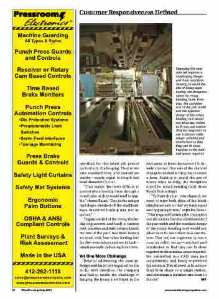
Stamping the new side rail requires a challenging flange- and-hem operation. Seeking to avoid the use of heavy wipe tooling, die designers opted for rotary bending tools. How- ever, the combina- tion of the part width and the standard design of the rotary bending tool would not allow two rollers to fit into one station. That led engineers to use a custom roller setup—notched and interlocked so that they can fit close together in the mini- mal space required.
Seyi press, to form the narrow 11⁄8-in.- wide channel. One side of the channel then gets crushed in the press to create a hem. Seeking to avoid the use of heavy wipe tooling, die designers opted for rotary bending tools (from Ready Technology).
“To form the nar row channel, we need to wipe both sides of the blank simultaneously so that we have equal and opposing forces,” explains Bauer. “That required forming the channel in one die station. But, the combination of the part width and the standard design of the rotary bending tool would not allow us to fit two rollers into one sta- tion. That led our engineers to use a custom roller setup—notched and interlocked so that they can fit close together in the minimal space required. We submitted our CAD data and requirements, and Ready engineered the solution. This allowed us to achieve final form shape in a single station, and eliminate a restrike/cam form in the die.” MF
