
Page 46 - MetalForming May 2014
P. 46
Resistance Fastener Welding
teners are brought into contact with the metal stamping. Conversely, exces- sive force will prematurely collapse the projections and lead to incomplete fusion.
Flaws? Read the Clues
Excessive weld spatter in or on the threads of the fastener can result from low electrode force, a short squeeze time, poor head follow up or excessive current.
Thread distortion, or the collapse of the nut body, can result from exces- sive weld time—alleviate this condition by shortening weld time and raising the current and force.
Experiencing hole misalignment or poor location of the fastener on the stamping? The most likely cause is the locating weld pin, or electrode mis- alignment.
Simple, reliable and standardized single-point RPW machines provide an answer and solve many problems. Once the process parameters of cur-
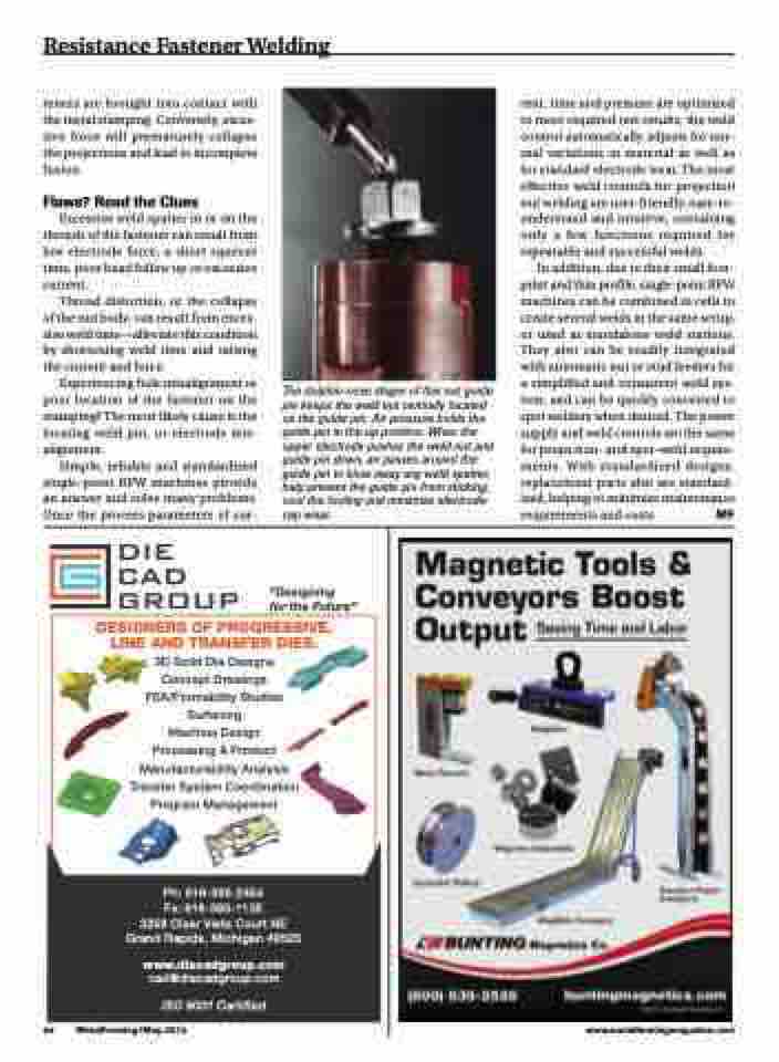
The dolphin-nose shape of this nut guide pin keeps the weld nut centrally located on the guide pin. Air pressure holds the guide pin in the up position. When the upper electrode pushes the weld nut and guide pin down, air passes around the guide pin to blow away any weld spatter, help prevent the guide pin from sticking, cool the tooling and minimize electrode- cap wear.
“Designing
for the Future”
rent, time and pressure are optimized to meet required test results, the weld control automatically adjusts for nor- mal variations in material as well as for standard electrode wear. The most effective weld controls for projection nut welding are user-friendly, easy-to- understand and intuitive, containing only a few functions required for repeatable and successful welds.
In addition, due to their small foot- print and thin profile, single-point RPW machines can be combined in cells to create several welds in the same setup, or used as standalone weld stations. They also can be readily integrated with automatic nut or stud feeders for a simplified and consistent weld sys- tem, and can be quickly converted to spot welders when desired. The power supply and weld controls are the same for projection- and spot-weld require- ments. With standardized designs, replacement parts also are standard- ized, helping to minimize maintenance requirements and costs. MF
DESIGNERS OF PROGRESSIVE, LINE AND TRANSFER DIES. 3D Solid Die Designs
Concept Drawings FEA/Formability Studies Surfacing
Machine Design
Processing & Product Manufacturability Analysis Transfer System Coordination Program Management
Ph: 616-365-2454
Fx: 616-365-1135
3258 Clear Vista Court NE Grand Rapids, Michigan 49525
www.diecadgroup.com
cad@diecadgroup.com
ISO 9001 Certified
44 MetalForming/May 2014
www.metalformingmagazine.com
