
Page 46 - MetalForming February 2014
P. 46
Tooling by Design
By Peter Ulintz
Improving Hole Burnish and Cut-Edge Quality
Shave operations generally are associated with bur- nished openings such as holes, but free-edge features also may be shaved. In fact, many die-cut features requiring close tolerances and burnished edges are good candidates for shaving.
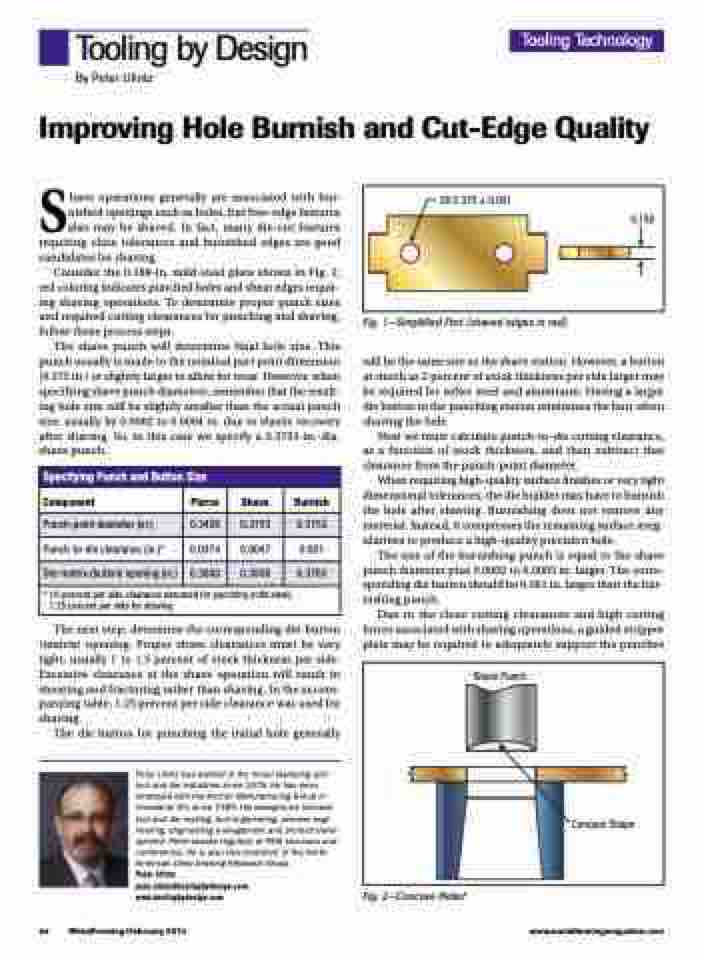
Consider the 0.188-in. mild-steel plate shown in Fig. 1; red coloring indicates punched holes and shear edges requir- ing shaving operations. To determine proper punch sizes and required cutting clearances for punching and shaving, follow these process steps.
The shave punch will determine final hole size. This punch usually is made to the nominal part print dimension (0.375 in.) or slightly larger to allow for wear. However, when specifying shave punch diameters, remember that the result- ing hole size will be slightly smaller than the actual punch size, usually by 0.0002 to 0.0004 in. due to elastic recovery after shaving. So, in this case we specify a 0.3753-in.-dia. shave punch.
Fig. 1—Simplified Part (shaved edges in red)
will be the same size as the shave station. However, a button as much as 2 percent of stock thickness per side larger may be required for softer steel and aluminum. Having a larger die button in the punching station minimizes the burr when shaving the hole.
Next we must calculate punch-to-die cutting clearance, as a function of stock thickness, and then subtract that clearance from the punch-point diameter.
When requiring high-quality surface finishes or very tight dimensional tolerances, the die builder may have to burnish the hole after shaving. Burnishing does not remove any material. Instead, it compresses the remaining surface irreg- ularities to produce a high-quality precision hole.
The size of the burnishing punch is equal to the shave punch diameter plus 0.0002 to 0.0003 in. larger. The corre- sponding die button should be 0.001 in. larger than the bur- nishing punch.
Due to the close cutting clearances and high cutting forces associated with shaving operations, a guided stripper plate may be required to adequately support the punches
Tooling Technology
2X 0.375 ± 0.001
0.188
Specifying Punch and Button Size
Component
Pierce
Shave
Burnish
Punch-point diameter (in.)
0.3426
0.3753
0.3753
Punch-to-die clearance (in.)*
0.0374
0.0047
0.001
Die-matrix (button) opening (in.)
0.3800
0.3800
0.3763
* 10-percent per side clearance assumed for punching (mild steel), 1.25 percent per side for shaving
The next step: determine the corresponding die-button (matrix) opening. Proper shave clearances must be very tight, usually 1 to 1.5 percent of stock thickness per side. Excessive clearance at the shave operation will result in shearing and fracturing rather than shaving. In the accom- panying table, 1.25 percent per side clearance was used for shaving.
The die button for punching the initial hole generally
Peter Ulintz has worked in the metal stamping and tool and die industries since 1978. He has been employed with the Anchor Manufacturing Group in Cleveland, OH, since 1989. His background includes tool and die making, tool engineering, process engi- neering, engineering management and product devel- opment. Peter speaks regularly at PMA seminars and conferences. He is also vice president of the North American Deep Drawing Research Group.
Peter Ulintz pete.ulintz@toolingbydesign.com www.toolingbydesign.com
Fig. 2—Concave Relief
Shave Punch
Concave Shape
44
MetalForming/February 2014
www.metalformingmagazine.com
