
Page 40 - MetalForming February 2014
P. 40
The Science of Forming
By Stuart Keeler
Getting a Grip on Friction
Let’s visit a press shop, where a stamped part is creating problems with excessive localized thinning in several locations (lack of surface area) and dimensional vari- ations (elastic stress springback patterns). Everyone points to the culprit—a poor lubricant. Workers are hauling out buckets of different lubricants from the storage shed and each is tried in turn.
Good action plan for a successful solution? Not really. The root cause: a change in friction, and the lubricant is only one component.
Tooling Technology
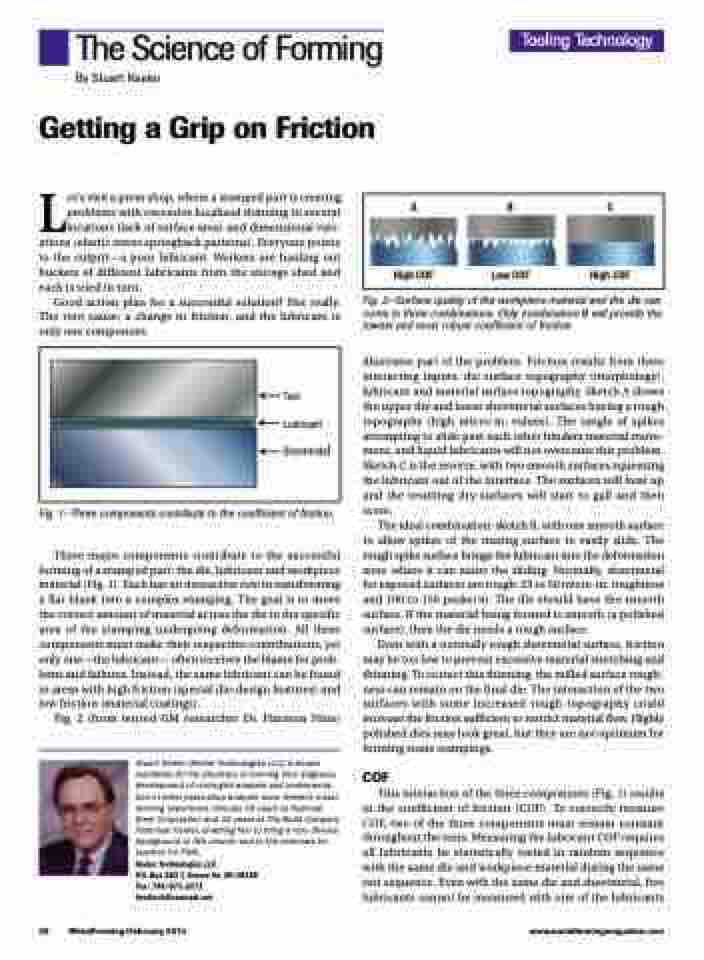
ABC
High COF Low COF High COF
Tool Lubricant Sheetmetal
Fig. 1—Three components contribute to the coefficient of friction.
Three major components contribute to the successful forming of a stamped part: the die, lubricant and workpiece material (Fig. 1). Each has an interactive role in transforming a flat blank into a complex stamping. The goal is to move the correct amount of material across the die to the specific area of the stamping undergoing deformation. All three components must make their respective contributions, yet only one—the lubricant— often receives the blame for prob- lems and failures. Instead, the same lubricant can be found in areas with high friction (special die-design features) and low friction (material coatings).
Fig. 2 (from retired GM researcher Dr. Harmon Nine)
Stuart Keeler (Keeler Technologies LLC) is known worldwide for his discovery of forming limit diagrams, development of circle-grid analysis and implementa- tion of other press-shop analysis tools. Keeler’s metal- forming experience includes 24 years at National Steel Corporation and 12 years at The Budd Company Technical Center, enabling him to bring a very diverse background to this column and to the seminars he teaches for PMA.
Keeler Technologies LLC
P.O. Box 283 | Grosse Ile, MI 48138 Fax: 734/671-2271 keeltech@comcast.net
Fig. 2—Surface quality of the workpiece material and the die can come in three combinations. Only combination B will provide the lowest and most robust coefficient of friction.
illustrates part of the problem. Friction results from three interacting inputs: die surface topography (morphology), lubricant and material surface topography. Sketch A shows the upper die and lower sheetmetal surfaces having a rough topography (high micro-in. values). The tangle of spikes attempting to slide past each other hinders material move- ment, and liquid lubricants will not overcome this problem. Sketch C is the reverse, with two smooth surfaces squeezing the lubricant out of the interface. The surfaces will heat up and the resulting dry surfaces will start to gall and then score.
The ideal combination: sketch B, with one smooth surface to allow spikes of the mating surface to easily slide. The rough spike surface brings the lubricant into the deformation zone where it can assist the sliding. Normally, sheetmetal for exposed surfaces are rough: 25 to 50 micro-in. roughness and 100 to 150 peaks/in. The die should have the smooth surface. If the material being formed is smooth (a polished surface), then the die needs a rough surface.
Even with a normally rough sheetmetal surface, friction may be too low to prevent excessive material stretching and thinning. To correct this thinning, the milled surface rough- ness can remain on the final die. The interaction of the two surfaces with some increased rough topography could increase the friction sufficient to restrict material flow. Highly polished dies may look great, but they are not optimum for forming some stampings.
COF
This interaction of the three components (Fig. 1) results in the coefficient of friction (COF). To correctly measure COF, two of the three components must remain constant throughout the tests. Measuring the lubricant COF requires all lubricants be statistically tested in random sequence with the same die and workpiece material during the same test sequence. Even with the same die and sheetmetal, five lubricants cannot be measured with one of the lubricants
38
MetalForming/February 2014
www.metalformingmagazine.com
