
Page 31 - MetalForming February 2014
P. 31
Accurate Simulation Starts with a Robust Material- Property Database
ATD’s ongoing design-software evo- lution also aims to improve its ability to accurately simulate new progres- sive-die strip models, and also to sup- port weld-fixture development. Enter Dynaform, with modules for estimating blank size and predict thinning and thickening; create complete die-face models, including binder and adden- dum, from part geometry; simulate and validate die designs and identify problem areas, as well as optimize designs to reduce wrinkling, thinning and tearing; and analyze a completed die to provide insights into stamping- production issues such as scrap shed- ding and material handling.
“Simulation has become an important tool for us,” shares Andras, “as we seek to control the development of our pro- gressive dies and simulate the process during strip development. We can easily flow data back and forth between VISI and Dynaform, to avoid excessive trou- bleshooting in the press, which can become quite time consuming and costly.
“The real benefit to simulation for us,” stresses Andras: “Creating a robust forming sequence and strip layout that we can pass on to our tool designer and builder with confidence that the die will run in production almost immediately.”
Moving up the learning curve as ATD engineers zero in on the benefits of Dynaform simulations, Andras points to the need to completely under- stand material properties in order to ensure accurate simulations. We’re talk- ing yield strength coefficient, k, n and r values, yield stress, precent elonga- tion, ultimate tensile, etc.
“We are creating our own library of material properties for the alloys we stamp, by sending material samples out for testing,” he says. “These are stored within Dynaform. This practice is particularly critical to accurate sim- ulation results when forming our more sensitive parts.”
Last but not least, engineers working in the ATD design center in Costa Rica employ Dynaform further downstream
in the die-develop-
ment process, to
develop press and
energy curves for the
company. “This
ensures we can run
specific dies in spe-
cific presses,” says
Andras. “And,
Dynaform can tell us,
by calculating form-
ing pressures
throughout a tool,
where we might
need to tweak the
tool, by adding nitrogen cylinders for example.”
Scanning Captures Toolmaker’s “Magic”
As much as its new software tools have enhanced the strip- and die- development process at ATD, the firm still must continue to work to overcome challenges related to increased part and assembly complexity, and the slew of new steels finding their way into automobiles. Here, more often than not a toolmaker must “work his magic,” says Andras, “and perform handwork on one or more die stations to get a die to run flawlessly in the press.”
Such “magic” often renders die sta- tions notably altered from their original CAD models. The inability to capture the result of these die-development activities often causes die-design data to be inaccurate at best and unusable at worst. In 2002, ATD purchased its first FaroArm capable of scanning form and cutting edges. In 2009, a new FaroArm was purchased, along with a laser scanner to capture the magic. ATD engineers employ the machine to acquire surface data and enable reverse engineering of die surfaces. This device has proven to be so useful that ATD acquired a second ScanArm for its Seville, OH facility. In addition, ATD has added a third machine for its sister facility in China. This allows designs to be easily updated after the tryout and development activity has been completed, which guarantees complete and accurate tool designs for each
www.metalformingmagazine.com
MetalForming/February 2014 29
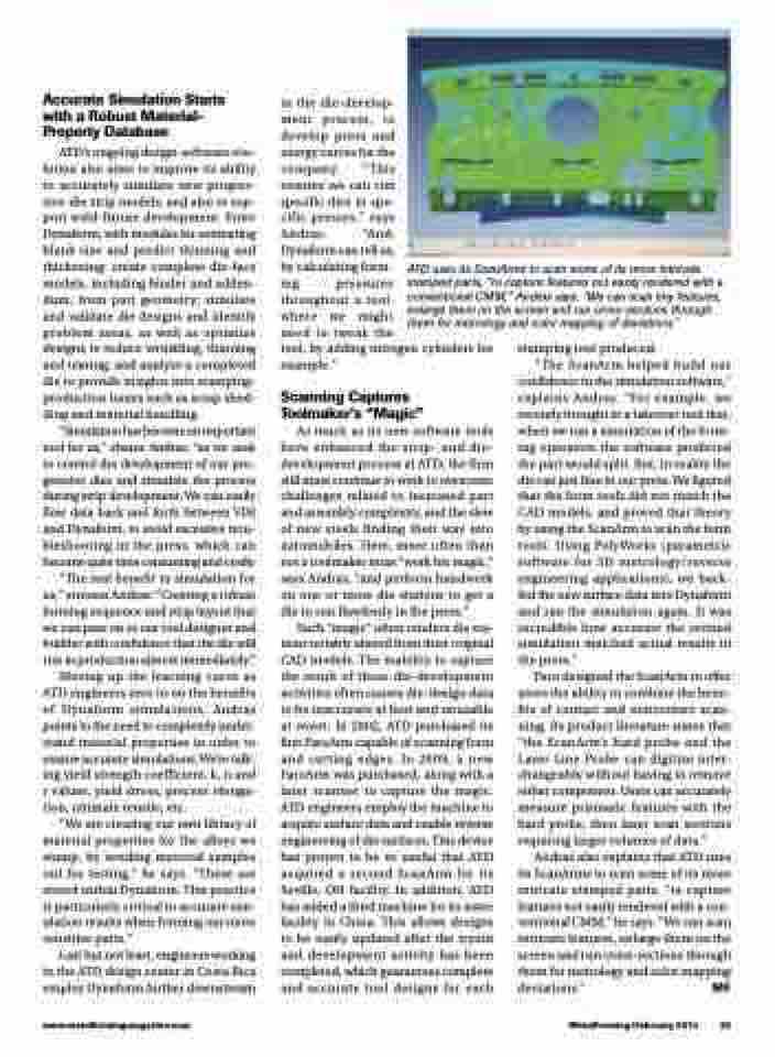
ATD uses its ScanArms to scan some of its more intricate stamped parts, “to capture features not easily rendered with a conventional CMM,” Andras says. “We can scan tiny features, enlarge them on the screen and run cross-sections through them for metrology and color mapping of deviations.”
stamping tool produced.
“The ScanArm helped build our
confidence in the simulation software,” explains Andras. “For example, we recently brought in a takeover tool that, when we ran a simulation of the form- ing operation the software predicted the part would split. But, in reality the die ran just fine in our press. We figured that the form tools did not match the CAD models, and proved that theory by using the ScanArm to scan the form tools. Using PolyWorks (parametric software for 3D metrology/reverse engineering applications), we back- fed the new surface data into Dynaform and ran the simulation again. It was incredible how accurate the revised simulation matched actual results in the press.”
Faro designed the ScanArm to offer users the ability to combine the bene- fits of contact and noncontact scan- ning. Its product literature states that “the ScanArm’s hard probe and the Laser Line Probe can digitize inter- changeably without having to remove either component. Users can accurately measure prismatic features with the hard probe, then laser scan sections requiring larger volumes of data.”
Andras also explains that ATD uses its ScanArms to scan some of its more intricate stamped parts, “to capture features not easily rendered with a con- ventional CMM,” he says. “We can scan intricate features, enlarge them on the screen and run cross-sections through them for metrology and color mapping deviations.” MF
