
Page 42 - MetalForming December 2013
P. 42
Tooling by Design
By Peter Ulintz
The Influence of Material Type on Die Design
Tooling Technology
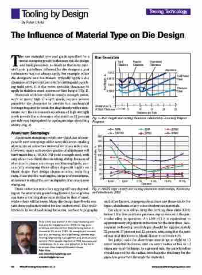
Burr Generation
Tight Regular Clearance Clearance
Engineered Clearance
0.002 0.0015 0.001 0.0005 0
Clearance as %
of Stock Thickness
Aluminum
Cold Rolled Steel
Stainless Steel
5 10
Clearance per Side
15 20 25
The raw material type and grade specified for a metal stamping greatly influences the die design and build processes, so much so that some rule- of-thumb guidelines followed by die designers and toolmakers may not always apply. For example, while die designers and toolmakers typically apply a die clearance of 10 percent per side for cutting and punch- ing mild steel, it is the worst possible clearance to apply to stainless steel in terms of burr height (Fig. 1).
Materials with low yield-to-tensile strength ratios, such as many high-strength steels, require greater punch-to-die clearance to provide the mechanical leverage required to break the slug cleanly with a min- imum burr. Recent research on advanced high-strength steels reveals that a clearance of as much as 21 percent per side may be required for optimum edge-stretching ability (Fig. 2).
Aluminum Stampings
Aluminum stampings weigh one-third that of com- parable steel stampings of the same thickness, making aluminum an attractive material for mass reduction. However, many automotive grades of aluminum will form much like a 100,000-PSI yield-strength steel, with only about two-thirds the stretching ability. Because of aluminum’s planar anisotropy and forming limits, suc- cessfully stamping these alloys depends highly on blank shape. Part design characteristics, including radii, draw depths, wall angles, steps and transitions, all interact to affect the cost and quality of an aluminum stamping.
Fig. 1—Burr height and cutting clearance relationship—courtesy Dayton Progress.
50XK TRIP780
590R DP780
DP590 DP980
180 160 140 120 100
80 60 40 20
0
Ream
Laser
1.1% Clearance
20.8%
6.4% 13.6%
Draw-reduction ratios for cupping will vary depend-
ing on the aluminum grade being formed. Some grades
can have a limiting draw ratio similar to that of steel, while others will be lower. Many die-design handbooks con- tain draw-reduction tables for low-carbon steel. Due to dif- ferences in workhardening behavior, surface topography
Peter Ulintz has worked in the metal stamping and tool and die industries since 1978. He has been employed with the Anchor Manufacturing Group in Cleveland, OH, since 1989. His background includes tool and die making, tool engineering, process engi- neering, engineering management and product devel- opment. Peter speaks regularly at PMA seminars and conferences. He is also vice president of the North American Deep Drawing Research Group.
Peter Ulintz pete.ulintz@toolingbydesign.com www.toolingbydesign.com
Fig. 2—AHSS edge stretch and cutting clearance relationships, Konieczny and Henderson, 2007.
and other factors, stampers should not use those tables for brass, aluminum or any other nonferrous materials.
For aluminum alloys, keep the limiting draw ratio (LDR) below 1.6 unless you have previous experience with the par- ticular alloy in question. An LDR of 1.6 is equivalent to approximately 38 percent reduction for the first draw. Sub- sequent redrawing percentages should be approximately 22 percent, 17 percent and 12 percent, assuming that the ratio of material thickness to blank diameter exceeds 0.25.
Set punch radii for aluminum stampings at eight to 10 times material thickness, and die entry radius at five to 10 times material thickness. As a general rule, the punch radius should exceed the die radius, to reduce the tendency for the punch to penetrate through the material.
40 MetalForming/December 2013
www.metalformingmagazine.com
Hole Expansion Ratio, %
Burr Height , in.
