
Page 48 - MetalForming August 2013
P. 48
Tooling by Design
By Peter Ulintz
Defining Acceptable Burr Height
Tooling Technology
T he maximum acceptable burr height for a metal stamp- ing is equal to 10 percent of sheetmetal thickness.
The above statement would be true if all stampings were produced from low-carbon steel less than 0.050 in. thick, using typical punch-to-die cutting clearances. However, this, like so many other metalforming “rules of thumb,” has been repeated by so many for so long that we’ve come to accept it as absolute fact without regard for its origin. The 10-percent burr-height rule can be found in publications as early as the nineteenth century, including J.L Lewis’ Dies and Die Making, published in 1897.
Why is the 10-percent burr-height rule of thumb often unreasonable or inappropriate? As burr heights begin to approach 0.003 in., they start to become noticeable. In some instances, burr heights greater than 0.005 in. can become dangerous, potentially cutting or otherwise harming assem- bly workers. Also, die-cut edges subjected to high tensile stresses—such as those seen in stretch flanging—can be very sensitive to edge quality and burr height. The quality of the cut edge, including burr height, can be the difference between producing a good part or not.
Note: Here’s one more example, also from J.L. Lewis’ book, of how the old metalforming rules of thumb may no longer be applicable. Lewis writes: “In the re-punching of brass and copper, the use of buttermilk as a lubricant will give bet- ter results than any oil or soap water that we have yet found.”
Today, a wide variety of material compositions, mechan- ical properties and thicknesses are routinely produced in metal-stamping dies, a far cry from the limited metallurgy and slab-rolling capabilities from the 19th century. As a result, one must discard many of the archaic rules of thumb and apply an engineering approach.
An engineering approach to establishing burr-height limits would recognize that cutting and punching impart shear stress- es in the workpiece material, and that these stresses relate
Peter Ulintz has worked in the metal stamping and tool and die industries since 1978. He has been employed with the Anchor Manufacturing Group in Cleveland, OH, since 1989. His background includes tool and die making, tool engineering, process engi- neering, engineering management and product devel- opment. He is vice-president of the North American Deep Drawing Research Group. Peter speaks regularly at PMA seminars and conferences and maintains the website, www.ToolingbyDesign.com. The site serves as a web-based source for the transfer of modern metal- forming technology and the advancement of “Perfor- mance-Based Die Engineering Strategies.”
Peter Ulintz
pete.ulintz@toolingbydesign.com, www.toolingbydesign.com
directly to the material’s ultimate tensile strength. Materials with high yield-to-tensile strength ratios (Inconel, for example) require tight punch-to-die cutting clearances, typically 5 to 8 per- cent of material thickness per side. These highly formable materials want to deform or extrude the hole feature rather than shear or cut, making burr-height control difficult to manage.
Materials with low yield-to-tensile strength ratios (many high-strength steels, for example) require greater punch-to- die clearance to provide the mechanical leverage required to break the slug cleanly with a minimum burr. In these instances, stampers apply engineering clearances—punch- to-die cutting clearances beyond the traditional 5 to 8 percent of material thickness per side. Engineering clearances result from extensive research conducted during the last 50 years.
Engineering clearances as great as 40 to 50 percent per side may be applied to very thin materials, depending on hole size and material type. Recent research with advanced high- strength steels (Konieczny and Henderson, 2007) indicate that as much as a 21-percent per-side clearance may be required for some materials. Lewis and his peers were unaware of such clearances.
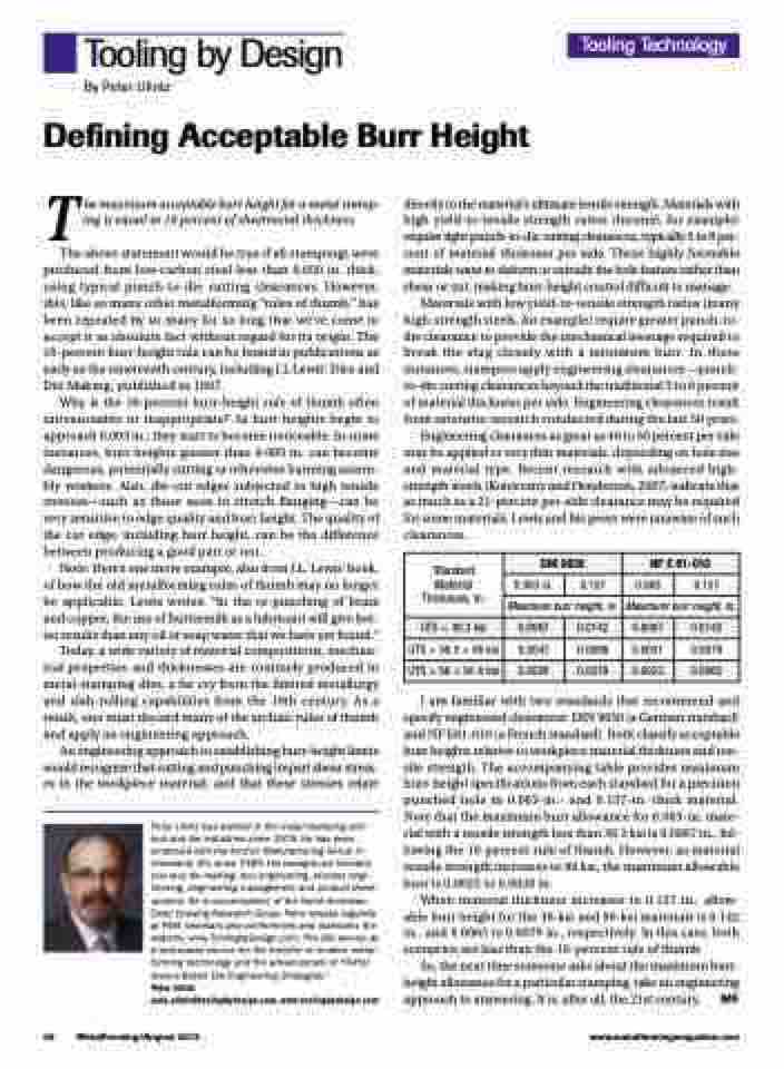
I am familiar with two standards that recommend and specify engineered clearances: DIN 9830 (a German standard) and NF E81-010 (a French standard). Both classify acceptable burr heights relative to workpiece material thickness and ten- sile strength. The accompanying table provides maximum burr-height specifications from each standard for a precision punched hole in 0.063-in.- and 0.157-in.-thick material. Note that the maximum burr allowance for 0.063-in. mate- rial with a tensile strength less than 36.3 ksi is 0.0067 in., fol- lowing the 10-percent rule of thumb. However, as material tensile strength increases to 90 ksi, the maximum allowable burr is 0.0023 to 0.0028 in.
When material thickness increases to 0.157 in., allow- able burr height for the 36-ksi and 90-ksi materials is 0.142 in., and 0.0063 to 0.0079 in., respectively. In this case, both scenarios are less than the 10-percent rule of thumb.
So, the next time someone asks about the maximum burr- height allowance for a particular stamping, take an engineering approach to answering. It is, after all, the 21st century. MF
Standard Material Thickness, in.
DIN 9830
NF E 81-010
0.063 in.
0.157
0.063
0.157
Maximum burr height, in.
Maximum burr height, in.
UTS < 36.3 ksi
0.0067
0.0142
0.0067
0.0142
UTS > 36.3 < 58 ksi
0.0047
0.0098
0.0031
0.0079
UTS > 58 < 91.4 ksi
0.0028
0.0079
0.0023
0.0063
46 MetalForming/August 2013
www.metalformingmagazine.com
