
Page 58 - MetalForming March 2013
P. 58
Tooling by Design
By Peter Ulintz
Aluminum Lightweighting Challenges
Lightweighting has become a common term in the auto- motive industry. It describes product-design activity that maximizes fuel efficiency to meet federal corpo- rate-average fuel-economy (CAFE) requirements through the reduction of vehicle mass. Currently, this is being achieved through the use of higher-tensile-strength steels, allowing automakers to reduce the thickness of metal stampings.
Last month we examined how high-strength steel can push press-line performance requirements well beyond the capa- bilities and limitations for which they were originally designed. But manufacturing challenges associated with lightweight stampings are not limited to high-strength steel; applications for aluminum stampings are growing in automotive applications.
Aluminum stampings weigh one-third that of compara- ble steel stampings of the same thickness, making the mate- rial attractive for mass-reduction efforts. But many auto- motive grades form much like 100,000-PSI yield-strength steel and only have about two-thirds the stretching ability of steel. Successful forming of aluminum, because of its planar anisotropy and forming limits, depends highly on blank shape. Design features, including radii, draw depths, wall angles, steps and transitions, interact to affect the cost and quality of the stamped aluminum part.
Immediately after exposure to air, aluminum forms a thin natural layer of aluminum oxide on the sheet surface that can break down during forming and abrade the tooling. This often requires an application of PVD, TD or other sur- face treatments to protect the tooling. A light overall lubri- cation should always be applied to both sides of the blank, even during blanking and shearing.
Aluminum also has one-third the elastic modulus of steel. This reduction in Young’s modulus increases the magnitude of springback by a factor of three compared to steel sheet of equivalent thickness and yield strength. The reduced elastic modulus also increases the likelihood of surface distortion such as wrinkling and oil canning. The ultimate aluminum
Peter Ulintz has worked in the metal stamping and tool and die industries since 1978. He has been employed with the Anchor Manufacturing Group in Cleveland, OH, since 1989. His background includes tool and die making, tool engineering, process engi- neering, engineering management and product devel- opment. He is vice-president of the North American Deep Drawing Research Group. Peter speaks regularly at PMA seminars and conferences and maintains the website, www.ToolingbyDesign.com. The site serves as a web-based source for the transfer of modern metal- forming technology and the advancement of “Perfor- mance-Based Die Engineering Strategies.”
Peter Ulintz
pete.ulintz@toolingbydesign.com, www.toolingbydesign.com
stamping stretches evenly and distributes strains uniform- ly when deformed.
Deep Drawing
Proper blank size is particularly important when deep drawing aluminum. A rectangular blank, often selected for simplicity and low cost, does not necessarily maximize formability. Designers optimize blank shapes through ana- lytical methods (forming simulations) or by trial and error. Regardless of the method chosen, developed blanks will vastly improve aluminum draw-forming processes.
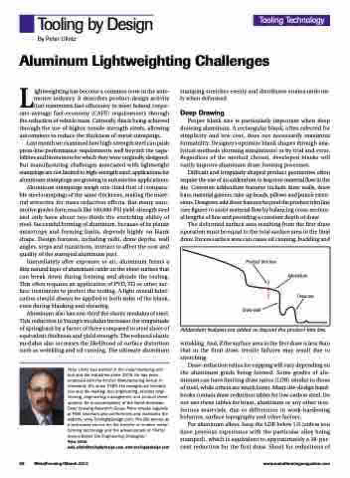
Difficult and irregularly shaped product geometries often require the use of an addendum to improve material flow in the die. Common addendum features include draw walls, draw bars, material gainers, take-up beads, pillows and punch exten- sions. Designers add these features beyond the product trim line (see figure) to assist material flow by balancing cross-section- al lengths of line and providing a constant depth of draw.
The deformed surface area resulting from the first draw operation must be equal to the total surface area in the final draw. Excess surface area can cause oil canning, buckling and
Tooling Technology
Product trim line
Draw wall
Addendum
Draw bar
Addendum features are added on beyond the product trim line.
wrinkling. And, if the surface area in the first draw is less than that in the final draw, tensile failures may result due to stretching.
Draw-reduction ratios for cupping will vary depending on the aluminum grade being formed. Some grades of alu- minum can have limiting draw ratios (LDR) similar to those of steel, while others are much lower. Many die-design hand- books contain draw-reduction tables for low-carbon steel. Do not use these tables for brass, aluminum or any other non- ferrous materials, due to differences in work-hardening behavior, surface topography and other factors.
For aluminum alloys, keep the LDR below 1.6 (unless you have previous experience with the particular alloy being stamped), which is equivalent to approximately a 38-per- cent reduction for the first draw. Shoot for reductions of
56 MetalForming/March 2013
www.metalformingmagazine.com
