
Page 40 - MetalForming November 2012
P. 40
Tooling by Design
By Peter Ulintz
Progressive-Die Strip Evaluation–Part III
In parts I and II of this series, we identified four primary process factors that influence the cost and quality of progressive dies:
• Station number factor, Fn
• Moment balancing factor, Fb
• Strip stability factor, Fs
• Feed height factor, Fh
Mathematically evaluating these factors and their corre-
sponding weighting factors—wn, wb, ws, wh— derives an evaluation score (Ev) for ranking several feasible strip layouts:
Ev =(wn xFn)+(wb xFb)+(ws xFs)+(wh xFh)
The designer or process engineer selects the weighting fac- tors by determining each evaluation factor contributes to the final evaluation score. The final evaluation score has relative meaning for different feasible strip layouts producing the same part. Therefore, it can be used to find the best solution for processing the particular part.
Let’s turn our attention to the influence of feed height fac- tor, which determines the quality of a strip layout based on the distance the strip must travel upward before feeding forward. The factor ranges from 10 (worst) to 100 (best).
Typically, the designer seeks to lift the stock as little as pos- sible: lifting takes time, and as lift height increases so must lift velocity or acceleration. Consequently, feed accuracy can suffer, or the strip can become unstable due to vibration and bounce caused by excessive acceleration. Increased feed rates, die strip vibrations and strip bounce can negatively affect part accuracy, often leading to more complicated die designs.
Seldom is the feed height for a progressive-die strip zero. Even if the strip remains completely flat, some lifting is required to break the oil seal created by lubricant trapped between the die surface and the strip.
Lifting of the die strip also proves necessary to ensure that
Peter Ulintz has worked in the metal stamping and tool and die industries since 1978. He has been employed with the Anchor Manufacturing Group in Cleveland, OH, since 1989. His background includes tool and die making, tool engineering, process engi- neering, engineering management and product devel- opment. He is vice-president of the North American Deep Drawing Research Group. Peter speaks regularly at PMA seminars and conferences and maintains the website, www.ToolingbyDesign.com. The site serves as a web-based source for the transfer of modern metal- forming technology and the advancement of “Perfor- mance-Based Die Engineering Strategies.”
Peter Ulintz pete.ulintz@toolingbydesign.com www.toolingbydesign.com
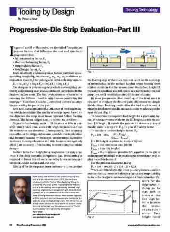
Fig. 1
the leading edge of the stock does not catch on die openings or mismatches in die surface heights when feeding from station to station. For that reason, a minimum feed height lift typically is specified, and referred to as a safety factor. For our purposes, we’ll establish a safety lift factor of 2 mm.
In most progressive dies, bending of the feed stock is required to produce the desired part; oftentimes bending is the dominant forming mode. After the feed stock is bent, it must be lifted above the die surface in order to advance to the next station (Fig. 1).
To determine the required feed height for a given strip lay- out, the designer must evaluate the lift height at each die sta- tion. Lift height, H, equals the greatest lift distance at any of the die stations (step 2 in Fig. 1), plus the safety factor.
To calculate the feed height factor, Fh:
Fh =100–90x (H–Hmin) (Hmax – Hmin)
H = lift height required for current layout
Hmin = the minimum possible lift
Hmin = S (safety height)
Hmax = the maximum possible lift, equal to the height of
an imaginary rectangle that encloses the formed part (Fig. 2) plus the safety factor, S.
For the process illustrated in Fig. 1:
Fh =100–90x(8–2)/(10–2)=32.5
When combined with the other primary factors—station
number factor, moment balancing factor and strip stability factor—the designer can now compute a final evaluation (Ev) score for the strip layout. In doing so, he may seek to increase the feed height fac- tor to increase the overall evaluation score. Feed height factor
Tooling Technology
Feed
S
H=5
S
H=8
Step 1
Step 2
10
38
MetalForming/November 2012
www.metalformingmagazine.com
Fig. 2
