
Page 90 - MetalForming October 2012
P. 90
Tooling by Design
By Peter Ulintz
Progressive-Die Strip Evaluation—Part II
To select the optimum strip layout for a given progres- sive-die stamped part, metalformers must compare and rank each possible layout using a relevant scoring sys- tem. Last month we looked at four primary evaluation factors, among the several factors influencing the cost and quality of a progressive die:
• Station number factor, Fn
• Moment balancing factor, Fb
• Strip stability factor, Fs
• Feed height factor, Fh
We can calculate an evaluation score (Ev), first proposed
by Lin and Sheu (International Journal of Production Research, 2010), based on the four evaluation factors and their corresponding weighting factors wn, wb, ws, wh:
Ev =(wn xFn)+(wb xFb)+(ws xFs)+(wh xFh)
The designer or process engineer specifies the weighting factors after determining the contribution of each evaluation factor to the final strip-evaluation score.
The four evaluation factors are formulated
to center the equivalent reaction forces are to the axis of the press ram.
The strip stability factor (F ) describes how reliably the s
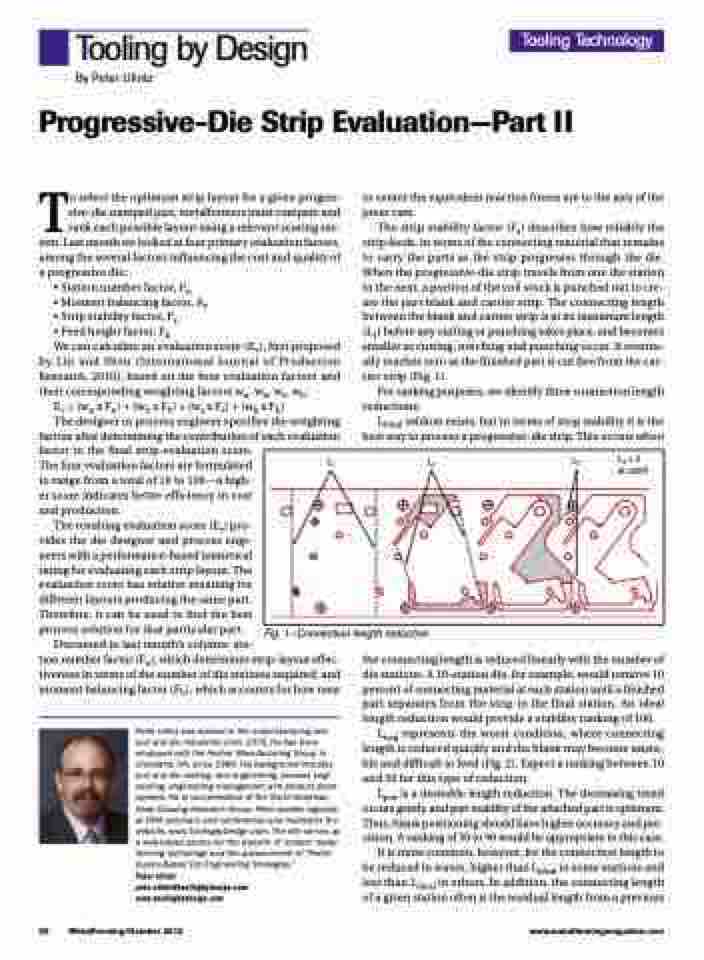
strip feeds, in terms of the connecting material that remains to carry the parts as the strip progresses through the die. When the progressive-die strip travels from one die station to the next, a portion of the coil stock is punched out to cre- ate the part blank and carrier strip. The connecting length between the blank and carrier strip is at its maximum length (L1) before any cutting or punching takes place, and becomes smaller as cutting, notching and punching occur. It eventu- ally reaches zero as the finished part is cut free from the car- rier strip (Fig. 1).
For ranking purposes, we identify three connection length reductions:
Lideal seldom exists, but in terms of strip stability it is the best way to process a progressive-die strip. This occurs when
to range from a total of 10 to 100—a high- er score indicates better efficiency in cost and production.
The resulting evaluation score (Ev) pro- vides the die designer and process engi- neers with a performance-based numerical rating for evaluating each strip layout. The evaluation score has relative meaning for different layouts producing the same part. Therefore, it can be used to find the best process solution for that particular part.
Fig. 1—Connection length reduction
Discussed in last month’s column: sta-
tion number factor (Fn), which determines strip-layout effec- tiveness in terms of the number of die stations required; and moment balancing factor (Fb), which accounts for how near
Peter Ulintz has worked in the metal stamping and tool and die industries since 1978. He has been employed with the Anchor Manufacturing Group in Cleveland, OH, since 1989. His background includes tool and die making, tool engineering, process engi- neering, engineering management and product devel- opment. He is vice-president of the North American Deep Drawing Research Group. Peter speaks regularly at PMA seminars and conferences and maintains the website, www.ToolingbyDesign.com. The site serves as a web-based source for the transfer of modern metal- forming technology and the advancement of “Perfor- mance-Based Die Engineering Strategies.”
Peter Ulintz pete.ulintz@toolingbydesign.com www.toolingbydesign.com
the connecting length is reduced linearly with the number of die stations. A 10-station die, for example, would remove 10 percent of connecting material at each station until a finished part separates from the strip in the final station. An ideal length reduction would provide a stability ranking of 100.
Lneg represents the worst condition, where connecting length is reduced quickly and the blank may become unsta- ble and difficult to feed (Fig. 2). Expect a ranking between 10 and 50 for this type of reduction.
Lpos is a desirable length reduction. The decreasing trend occurs gently, and part stability of the attached part is optimum. Thus, blank positioning should have higher accuracy and pre- cision. A ranking of 50 to 90 would be appropriate in this case.
It is more common, however, for the connection length to be reduced in waves, higher than Lideal in some stations and less than Lideal in others. In addition, the connecting length of a given station often is the residual length from a previous
Tooling Technology
L1 L2 L3L4=0 at cutoff
88 MetalForming/October 2012
www.metalformingmagazine.com
