
Page 53 - MetalForming September 2012
P. 53
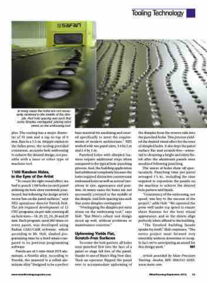
  In many cases the holes are not neces- sarily centered in the middle of the dim- ple. And hole spacing was such that some dimples overlapped, placing extra stress on the embossing tool.
ples. The tooling has a major diame- ter of 35 mm and a top-to-top of 6 mm. Run in a 3.5-in. Strippit station in the Safan press, the tooling provided consistent, accurate hole embossing to achieve the desired design, not pos- sible with a laser or other type of machine tool.
1100 Random Holes, in the Eyes of the Artist
“To create the right visual effect, we had to punch 1100 holes on each panel utilizing six hole sizes randomly posi- tioned, but following the design artist’s vector line on the panel surfaces,” says NES operations director Patrick Holt. The job required development of 12 CNC programs, six per side covering all six hole sizes—18, 20, 22, 24, 26 and 28 mm. Each program, used 200 times on every panel, was developed using Radan CAD/CAM software, which according to Mr. Holt, slashed pro- gramming time by a third when com- pared to its previous programming software.
Panels are of 3-mm-thick J57S alu- minum, a Novelis alloy. According to Novelis, the material is a rolled alu- minum alloy “designed to be a perfect
base material for anodizing and creat- ed specifically to meet the require- ments of modern architecture.” NES worked with two panel sizes, 3.6 by 2 m and2.4by2m.
Punched holes with dimpled fea- tures require additional steps when compared to the typical hole-punching process. And, the building application had additional complexity because the holes required distinctive countersunk embossed holes as well as several vari- ations in size, appearance and posi- tion. In many cases the holes are not necessarily centered in the middle of the dimple. And hole spacing was such that some dimples overlapped.
“Overlapping the dimples put extra stress on the embossing tool,” says Holt. “But Mate’s robust tool design stood up well, without problems or maintenance concerns.”
Upforming Yields Flat, Scratch-Free Surfaces
To create the hole pattern, all holes were punched first into the face of a panel so slugs fell free of the panel, thanks to use of Mate’s Slug Free dies. Then an operator flipped the panel over to accommodate upforming of
the dimples from the reverse side into the punched holes. This process yield- ed the desired visual effect for the rows of dimpled holes. It also kept the panel surface flat and scratch-free—essen- tial to obtaining a bright and shiny fin- ish after the aluminum panels were anodized following punching.
The waves of holes show off spec- tacularly. Punching time per panel averaged 11⁄2 hr., including the time required to reposition the panels on the machine to achieve the desired hole pattern and finish.
“Consistency of the embossing, not speed, was key to the success of the project,” adds Holt. “We operated the press well under top speed to ensure sheet flatness for the best visual appearance, and so the sheets align perfectly when affixed to the building.
“The finished building facade speaks for itself,” Holt continues. “The entire project went forward very smoothly without downtime or scrap. In fact, we’re anticipating an award for this design work.” MF
Article provided by Mate Precision Tooling, Anoka, MN: 800/541-0285; www.mate.com.
www.metalformingmagazine.com
MetalForming/September 2012 51
Tooling Technology
