
Page 39 - MetalForming March 2012
P. 39
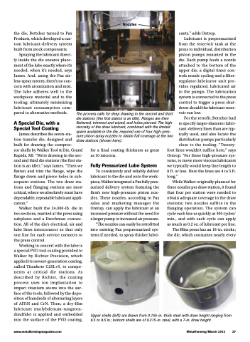
 Nozzles
   the die, Bettcher turned to Pax Products, which developed a cus- tom lubricant-delivery system built from stock components.
Spraying the lubricant direct- ly inside the die ensures place- ment of the lube exactly where it’s needed, when it’s needed, says James. And, using the Pax air- less-spray system, there’s no con- cern with atomization and mist. The lube adheres well to the workpiece material and to the tooling, ultimately minimizing lubricant consumption com- pared to alternative methods.
A Special Die, with a Special Tool Coating
The process calls for deep drawing in the second and third die stations (the first station is an idle). Flanges are then flattened, trimmed and wiped, and holes pierced. The high viscosity of the draw lubricant, combined with the limited space available in the die, required use of four high-pres- sure piston spray nozzles to obtain full coverage at the two draw stations (shown here).
cants,” adds Ontrop.
Lubricant is prepressurized
from the reservoir tank at the press to individual, distribution piston pumps mounted in the die. Each pump feeds a nozzle attached to the bottom of the upper die; a digital timer con- trols nozzle cycling and a filter- regulator-lubricator unit pro- vides regulated, lubricated air to the pumps. The lubrication system is connected to the press control to trigger a press shut- down should the lubricant reser- voir run low.
For the retrofit, Bettcher had to specify larger-diameter lubri- cant-delivery lines than are typ- ically used, and also locate the distribution pumps particularly close to the tooling. “Twenty-
James describes the seven-sta-
tion transfer die, designed and
built for drawing the compres-
sor shells by Walker Tool & Die, Grand Rapids, MI. “We’re drawing in the sec- ond and third die stations (the first sta- tion is an idle),” says James. “Then we flatten and trim the flange, wipe the flange down and pierce holes in sub- sequent stations. The two draw sta- tions and flanging stations are most critical, where we absolutely must have dependable, repeatable lubricant appli- cation.”
Walker built the 24,000-lb. die in two sections, married at the press using subplates and a Dutchman connec- tion. All of the die’s electrical, air and lube lines interconnect so that only one line for each service connects to the press control.
Working in concert with the lube is a special PVD tool coating provided to Walker by Richter Precision, which applied its newest-generation coating, called Titankote C2SL+S, to compo- nents at critical die stations. As described by Richter, the coating process uses ion implantation to impart titanium atoms into the sur- face of the tools, followed by the depo- sition of hundreds of alternating layers of AlTiN and CrN. Then, a dry-film lubricant (molybdenum-tungsten- disulfide) is applied and embedded into the surface of the PVD coating,
for a final coating thickness as great as 10 microns.
Fully Pressurized Lube System
To consistently and reliably deliver lubricant to the die and onto the work- piece, Walker integrated a Pax fully pres- surized delivery system featuring the firm’s new high-pressure piston noz- zles. These nozzles, according to Pax sales and marketing manager Pat Ontrop, can apply the lubricant at an increased pressure without the need for a larger pump or increased air pressure.
“The nozzles can easily be retrofitted into existing Pax prepressurized sys- tems if needed, to spray thicker lubri-
foot lines wouldn’t suffice here,” says Ontrop. “For these high-pressure sys- tems, to move more viscous lubricants we typically would keep line length to 8ft.orless.Herethelinesare4to5ft. long.”
While Walker originally planned for three nozzles per draw station, it found that four per station were needed to obtain adequate coverage in the draw stations; two nozzles suffice in the flanging operation. The system can cycle each line as quickly as 300 cycles/ min., and with each cycle can apply as much as 0.2 oz. of lubricant per line.
The Bliss press has an 18-in. stroke; the die, which consumes nearly every
  www.metalformingmagazine.com
MetalForming/March 2012 37
Upper shells (left) are drawn from 0.155-in.-thick steel with draw height ranging from 6.5 to 8.5 in.; bottom shells are of 0.215-in. steel, with a 7-in. draw height.
