
Page 28 - MetalForming March 2012
P. 28
tional room for research and develop- ment and to allow for testing of its new modular die designs.
More Choices, More Flexibility
“We look at part volumes and com- plexity to develop dies better aligned with what the customer really needs,” says Dave Bachelier, Oberg’s director of engineering, discussing the firm’s foray into modular die designs. “So rather than dictate to the customer—either an outside customer or our internal press- rooms—the style/quality of the die we’ll build, we now can offer more choices and more flexibility.”
Traditionally, about 85 percent of the dies designed and built by Oberg are for outside customers. The remain- der supports its two stamping shops— in Sarver, PA, and in Tecate, Mexico, just south of San Diego, CA. As Oberg’s customer base has evolved, so has its toolroom and, as described above, its approach to die design and build. Series I dies (“Oberg dies”) now account for only 10 percent of the tools it devel- ops, says Dave Rugaber, executive vice president of sales and marketing. The majority of its dies (60 percent) fall under the category of Series II, the remainder Series III. While nearly all die assembly occurs at the company’s Freeport facility, it operates a machin- ing, grinding and EDM facility in Costa Rica that supplies about 30 percent of its die components.
“To scale back to Series II dies,” explains Bachelier, “rather than use individual punch-die sections for easy replacement, we’ll gang sections together and incorporate more wire cutting. Sensors typically will be surface mounted rather than buried in the die, and are connected with individual cables rather than interconnected with one main cable running to the con- troller.” Series II dies typically are designed for annual part volumes as low as 500,000 and up to 100 million.
Series III tools, for part volumes of 50,000 pieces to 200,000/yr., typically use purchased die sets and not much
carbide, unless a specific area looks to be high wear. “Otherwise, we use tool steel or PM steels,” says Bachelier, “and we may specify a box stripper rather than a spring stripper.”
In most cases, medical and defense parts are run on Series I or Series II
dies—it all depends on evaluating the task at hand, not only part volumes and program life but also tolerances and other quality concerns. For exam- ple, Series I dies promise punch-to- die clearance of less than 0.0008 in., with die clearance of Series II dies equal to or greater than 0.0008 in.
“Most customers ask us to build them a die based on what we think they need,” Bachelier continues. “We have the freedom to look at expected tool life, form complexity and other program parameters and, relying our stamping experience and expertise, develop the best die for the job at hand.”
Lead-Time Reduction Starts in Design
With a more diverse customer base than ever before, Oberg is able to lever- age some of the design features it engi- neers for one customer and apply those features for its other customers’ proj- ects. “Our CAD system stores design standards into automated design pro- grams,” says Bachelier, “which stream- lines design for the next customer. For example, we can keep dowel and screw holes in similar locations to reduce programming time, and use off-the- shelf finished components.”
This standardization has blossomed in the last couple of years—from engi- neering through the toolroom—and allowed Oberg to reduce programming time by at least 30 percent in most cases. And, as programming time has dropped so has cycle time (from the time die steel is cut to when a die hits the assembly bench)—as much as 50 percent in the last 5 yr., explains Bill Wallace, Oberg’s stamping-plant tool- room manager.
“We monitor each work center with our MRP system (Infor System 10) and track performance,” Wallace explains. “Last year the tooling division enjoyed a 95-percent on-time delivery rate. Using the MRP system, we can monitor work load compared to capacity at each work station, and with that data in
TOOLROOM TECHNOLOGY
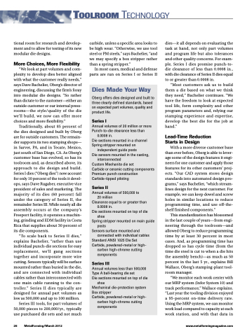
Dies Made Your Way
Oberg offers dies designed and built to three clearly defined standards, based on expected part volumes, quality and product life.
Series I
Annual volumes of 20 million or more Punch-to-die clearance less than
0.0008 in.
Die sections mounted in a channel Spring stripper mounted on
independent guide posts
Die sensors mounted in the casting,
interconnected
Custom Meehanite die set
Carbide or ceramic cutting components Premium punch construction Carbide-tipped piloting
Series II
Annual volumes of 500,000 to 20 million
Clearance equal to or greater than 0.0008 in.
Die sections mounted on top of die shoe
Spring stripper mounted on main guide posts
Sensors surface mounted and connected with individual cables
Standard ANSI 1025 Die Set Carbide, powdered-metal or high-
carbon high-chrome cutting components
Series III
Annual volumes less than 500,000 Type A ball-bearing die set
Die sections mounted on top of die
shoe
Mechanical die-protection system Box stripper
Carbide, powdered-metal or high-
carbon high-chrome cutting components
26 MetalForming/March 2012
www.metalformingmagazine.com
