
Page 17 - MetalForming January 2012
P. 17
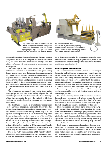
  Fig. 2—The third type of cradle—a cradle- feeder straightener—unwinds, straightens and feeds directly into the press without the need for a slack loop, making it a very compact and self-contained coil-feeding system.
horizontal loop. Of the three configurations, this style requires the greatest amount of floor space due to the horizontal loop, but lends itself well to quick coil changes with the addition of a spare coil load ramp and an unobstructed rear loading area.
The inline style of coil cradle unwinds the coil from the bottom into a vertical or overhead loop. This space-saving design creates a loop area that does not consume as much floor space as the combination configuration, although it can require substantial vertical height. Inline coil cradles are available with only a pair of pinch rolls to assist in peeling the material off of the coil, or they can incorporate a pow- ered straightener. Basic models for small coils pay off direct- ly from the nest rollers without the aid of pinch rolls or a straightener.
The inline design proves particularly useful for threading heavy-gauge material, since the leading edge of the coil enters the pinch rolls close to the nest rolls. A disadvantage of this style: Access to the nest rolls typically is blocked, requiring coil loading from the top with an overhead crane or lift truck.
The third type of cradle—a cradle-feeder straightener (CFS)—unwinds, straightens and feeds directly into the press without the need for a slack loop, making it a very com- pact and self-contained coil-feeding system (Fig. 2). A CFS typically receives power from one or more closed-loop servo drives, and pays off from the bottom or top of the coil. This style provides the same advantages as the inline style, but allows the use of a loading ramp for quick coil changes. Because this style requires that coil feeding start and stop in unison with the feed motion, a CFS requires significantly more horsepower than the other cradle styles, which feed into a slack loop and unwind in a continuous operation.
Due to the vastly increased load, a CFS typically is limit- ed to slower-speed applications, and may prove more cost- ly than the other cradle styles due to the use of high-power
Fig. 3—Nonpowered reels,
also known as pull-off reels, typically feature only a small fixed-speed threading drive or, in some cases with smaller coils or light gauge material, no drive at all.
servo drives. Additionally, the CFS concept generally is not recommended for use with long progressive dies, since a CFS does not allow for an effective pilot release unless the entire straightener bank is piloted.
Centering/Horizontal Reels
The second type of coil unwinder, known as a centering or horizontal reel, is the most common and versatile used by metalformers. These setups hold the coil by its inside diam- eter over an expanding arbor assembly that grips the coil’s inside diameter. Reels prove ideal for light- to medium- gauge material or for nonmarking applications, since their designs avoid contact with the outer wraps of the material as it unwinds. However, reels also can be used for heavy-gauge or high-strength materials if outfitted with the necessary equipment to safely contain coil clockspring and assist the threading operation.
Coil reels come in powered and nonpowered versions. Powered reels—motorized with a loop control for payoff into a slack loop—find use in applications that don’t require straightening, although they also can be used with a pull- through straightener powered by a feeder at the press.
Nonpowered reels, also known as pull-off reels (Fig. 3), typ- ically feature only a small fixed-speed threading drive or, in some cases with smaller coils or light gauge material, no drive at all. Pull-off reels rely on a power straightener or a set of pinch rolls to pull the material off of the coil during automatic operation. These reels typically feature a drag-tensioning device to maintain back tension, preventing loop slack and material distortion.
Reels come in numerous configurations, the most com- mon being a single-mandrel cantilevered style. These typically are offered in capacities from 500 to 60,000 lb., in widths to 78 in. Metalformers can opt for stationary or traveling mod- els—a traveling reel can quickly be repositioned upon detec- tion of misalignment.
www.metalformingmagazine.com
MetalForming/January 2012 15
