
Page 38 - MetalForming February 2011
P. 38
Tooling by Design
By Peter Ulintz
Managing Press Loads, Part 2: Press Selection
Maintaining an even distribution of the work load across the slide face (ram) helps ensure good part quality, improves die life and reduces press main- tenance. As discussed last month, when the working forces
connection significantly reduces the seesaw effect when the loads are not centered. However, this does not mean setting a die in a machine with a two-point connection is a cure-all for poor die engineering and excessive slide tipping.
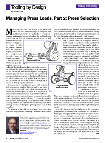
A slide with a two-point connection and single end drive (Fig. 1) can be subjected to angular misalign- ment caused by the torque being transmitted through the crankshaft. This angular misalign- ment causes the press slide nearest the drive system to reach bottom-dead-center first. Add a twin-end drive arrangement (Fig. 2), driving the crankshaft equally from both ends, and the result is much greater accuracy, particularly under load.
Wide-spaced slide connections also will com- bat the negative effects of off-center loading. By placing the connection points toward the outside
of the slide, the increased distance between the con- nection points increases slide stability and enables the press to resist tipping under off-center loads. This can be particularly benefi- cial when stamping higher- strength steels, where unbalanced loads can be particularly troublesome.
Another press feature to look for: a lube-free pre- loaded roller slide guide.
These zero-clearance systems help minimize the affects of slide-tipping conditions. Zero clearance improves slide guid- ing while the system’s preloaded characteristic provides immediate resistance to any lateral slide movement caused by off-center loads, keeping it parallel throughout the press stroke.
As a rule, the potential for misalignment due to ram tip- ping should be managed or eliminated via die design. Although it is not practical to design and build dies with per- fectly centered loading, it also is not wise to allow the press system to compensate for extreme off-center loading con- ditions. When excessive tipping moments are present, it is best to redistribute and balance the cutting and forming loads as evenly as possible, usually by revising the die design; offsetting the placement of the die in the press; or by providing offsetting forces or “dummy loads,” such as coin- ing an area of the stamping that ends up as trim scrap in later die operations. MF
in a die are not distributed evenly, the slide can tip move laterally in the
direction of the great-
est force. If this
movement occurs with the punches engaged with other die components, excessive wear or damage can occur.
and
Fig. 1
Tooling Technology
Nongearded Drive
An important first
step in managing die-
tipping moments:
evaluating the strip layout and the timing of progressive- die stations. The position of the various die stations as the die closes will alert the stamper to any tipping moment present. Good progressive-die engineering practices include a complete evaluation and balancing of loads generated at each die station. However, even the best practices can be defeated when die tipping is caused by improper press selection.
Single-Geared Twin-End Drive
Setting a die in a straightside press with a single slide connection requires that the load be carefully centered under the slide connection. Although a cen- tered load is always good practice, it is particularly important in this type of press. Visualize the slide in a single-connection press acting as a seesaw, with the slide connection acting as the fulcrum. A centered stamping load prevents slide tipping, but a slight unbalance in the loading condition will tip the slide, transferring some of the working pressure to the press gibbing rather than to the press bed.
Fortunately, straightside presses having two connection points are very common. Selecting a press with a two-point
Peter Ulintz has worked in the sheetmetal-forming industry since 1978. His background includes tool and die making, tool and process engineering, engi- neering management and product development. Peter also operates the website www.ToolingbyDesign.com, a source for the transfer of modern metalforming and tool-and-die technology, and which promotes the use of “Performance-Based Die Engineering Strategies.” Peter Ulintz
pete.ulintz@toolingbydesign.com www.toolingbydesign.com
Fig. 2
36 MetalForming/February 2011
www.metalformingmagazine.com
