
Page 38 - MetalForming January 2011
P. 38
Tooling by Design By Peter Ulintz
Managing Press Loads
Limiting the working loads of your presses to 80-percent of the maximum rated capacity is a common practice with many companies to ensure long machine life. But press selection often is determined by process engineering or tool engineering prior to tool construction. At this early phase of die development actual pressing forces only can be estimated. Only after the die is built and set in the press for the first time can the actual stamping loads be determined using press tonnage monitors. If actual tonnage exceeds the planned loading (tonnage), the die setter and engineer should consult to determine if the loading conditions are acceptable for the assigned machine.
Often overlooked is the fact that an even distribution of the work load across the slide face (ram) is equally important. Ignoring load distribution can lead to die damage and even- tually press damage, even when stamping loads remain well below the maximum rating of the press.
Maintaining the correct punch-to-die clearance is a pri- mary concern for producing high-quality stampings. When the working forces in a stampings die are not distributed evenly across the press slide, the slide will tip and move lat- erally in the direction of the greatest force. When the load is not centered under the press ram, critical die clearances may be altered. If this movement occurs while punches are engaged with other die components, excessive wear or dam- age can occur. Rapid die wear increases die maintenance costs and compromises the dimensional consistency of the stampings being produced. Unfortunately, some tooling engineers, process engineers, and setup personnel may not be aware of the negative effects of off-center loading on part quality and die life. As a result, dies will be designed, manufactured and installed in presses without consideration to centering the load.
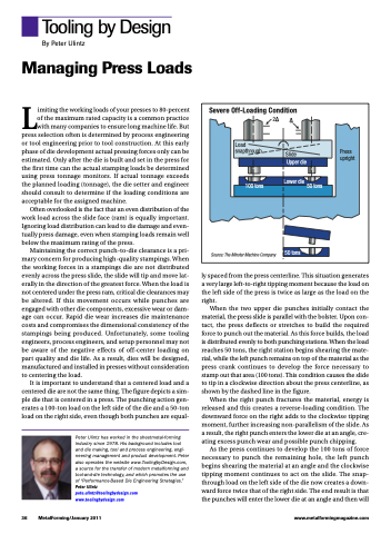
It is important to understand that a centered load and a centered die are not the same thing. The figure depicts a sim- ple die that is centered in a press. The punching action gen- erates a 100-ton load on the left side of the die and a 50-ton load on the right side, even though both punches are equal-
Peter Ulintz has worked in the sheetmetal-forming industry since 1978. His background includes tool and die making, tool and process engineering, engi- neering management and product development. Peter also operates the website www.ToolingbyDesign.com, a source for the transfer of modern metalforming and tool-and-die technology, and which promotes the use of “Performance-Based Die Engineering Strategies.” Peter Ulintz
pete.ulintz@toolingbydesign.com www.toolingbydesign.com
ly spaced from the press centerline. This situation generates a very large left-to-right tipping moment because the load on the left side of the press is twice as large as the load on the right.
When the two upper die punches initially contact the material, the press slide is parallel with the bolster. Upon con- tact, the press deflects or stretches to build the required force to punch out the material. As this force builds, the load is distributed evenly to both punching stations. When the load reaches 50 tons, the right station begins shearing the mate- rial, while the left punch remains on top of the material as the press crank continues to develop the force necessary to stamp out that area (100 tons). This condition causes the slide to tip in a clockwise direction about the press centerline, as shown by the dashed line in the figure.
When the right punch fractures the material, energy is released and this creates a reverse-loading condition. The downward force on the right adds to the clockwise tipping moment, further increasing non-parallelism of the slide. As a result, the right punch enters the lower die at an angle, cre- ating excess punch wear and possible punch chipping.
As the press continues to develop the 100 tons of force necessary to punch the remaining hole, the left punch begins shearing the material at an angle and the clockwise tipping moment continues to act on the slide. The snap- through load on the left side of the die now creates a down- ward force twice that of the right side. The end result is that the punches will enter the lower die at an angle and then will
Severe Off-Loading Condition
2
Load
snapthrough Slide Press
upright
100 tons
Upper die
Lower die
50 tons
50 tons
Source: The Minster Machine Company
36 MetalForming/January 2011
www.metalformingmagazine.com
