
Page 25 - MetalForming March 2010
P. 25
50
40
30
20
10
0
1 2 3 4 5 6 7 8 9 10 Location in Stamping
(Circle Number)
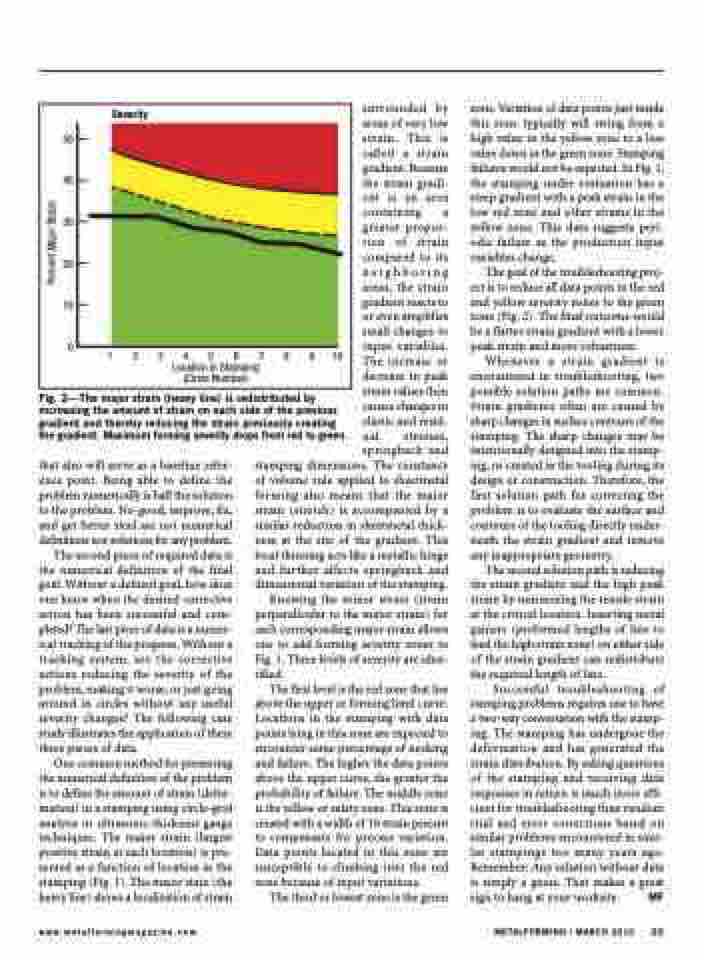
Severity
Fig. 2—The major strain (heavy line) is redistributed by increasing the amount of strain on each side of the previous gradient and thereby reducing the strain previously creating the gradient. Maximum forming severity drops from red to green.
surrounded by areas of very low strain. This is called a strain gradient. Because the strain gradi- ent is an area containing a greater propor- tion of strain compared to its neighboring areas, the strain gradient reacts to or even amplifies small changes to input variables. The increase or decrease in peak strain values then causes changes in elastic and resid- ual stresses, springback and
zone. Variation of data points just inside this zone typically will swing from a high value in the yellow zone to a low value down in the green zone. Stamping failures would not be expected. In Fig. 1, the stamping under evaluation has a steep gradient with a peak strain in the low red zone and other strains in the yellow zone. This data suggests peri- odic failure as the production input variables change.
The goal of the troubleshooting proj- ect is to reduce all data points in the red and yellow severity zones to the green zone (Fig. 2). The final outcome would be a flatter strain gradient with a lower peak strain and more robustness.
Whenever a strain gradient is encountered in troubleshooting, two possible solution paths are common. Strain gradients often are caused by sharp changes in surface contours of the stamping. The sharp changes may be intentionally designed into the stamp- ing, or created in the tooling during its design or construction. Therefore, the first solution path for correcting the problem is to evaluate the surface and contours of the tooling directly under- neath the strain gradient and remove any inappropriate geometry.
The second solution path is reducing the strain gradient and the high peak strain by minimizing the tensile strain at the critical location. Inserting metal gainers (preformed lengths of line to feed the high strain zone) on either side of the strain gradient can redistribute the required length of line.
Successful troubleshooting of stamping problems requires one to have a two-way conversation with the stamp- ing. The stamping has undergone the deformation and has generated the strain distribution. By asking questions of the stamping and receiving data responses in return is much more effi- cient for troubleshooting than random trial and error corrections based on similar problems encountered in simi- lar stampings too many years ago. Remember: Any solution without data is simply a guess. That makes a great sign to hang at your worksite. MF
that also will serve as a baseline refer- ence point. Being able to define the problem numerically is half the solution to the problem. No-good, improve, fix, and get better steel are not numerical definitions nor solutions for any problem.
The second piece of required data is the numerical definition of the final goal. Without a defined goal, how does one know when the desired corrective action has been successful and com- pleted? The last piece of data is a numer- ical tracking of the progress. Without a tracking system, are the corrective actions reducing the severity of the problem, making it worse, or just going around in circles without any useful severity changes? The following case study illustrates the application of these three pieces of data.
One common method for presenting the numerical definition of the problem is to define the amount of strain (defor- mation) in a stamping using circle-grid analysis or ultrasonic-thickness gauge techniques. The major strain (largest positive strain at each location) is pre- sented as a function of location in the stamping (Fig. 1). The major stain (the heavy line) shows a localization of strain
stamping dimensions. The constancy of volume rule applied to sheetmetal forming also means that the major strain (stretch) is accompanied by a similar reduction in sheetmetal thick- ness at the site of the gradient. This local thinning acts like a metallic hinge and further affects springback and dimensional variation of the stamping.
Knowing the minor strain (strain perpendicular to the major strain) for each corresponding major strain allows one to add forming severity zones to Fig. 1. Three levels of severity are iden- tified.
The first level is the red zone that lies above the upper or forming limit curve. Locations in the stamping with data points lying in this zone are expected to encounter some percentage of necking and failure. The higher the data points above the upper curve, the greater the probability of failure. The middle zone is the yellow or safety zone. This zone is created with a width of 10 strain percent to compensate for process variation. Data points located in this zone are susceptible to climbing into the red zone because of input variations.
The third or lowest zone is the green
www.metalformingmagazine.com
METALFORMING / MARCH 2010 23
Percent Major Strain
