
Page 14 - MetalForming December 2009
P. 14
Continuous
Coil-Fed Laser
Blanking
...edited from a white paper from Automatic Feed Co., Napoleon, OH; www.automaticfeed.com.
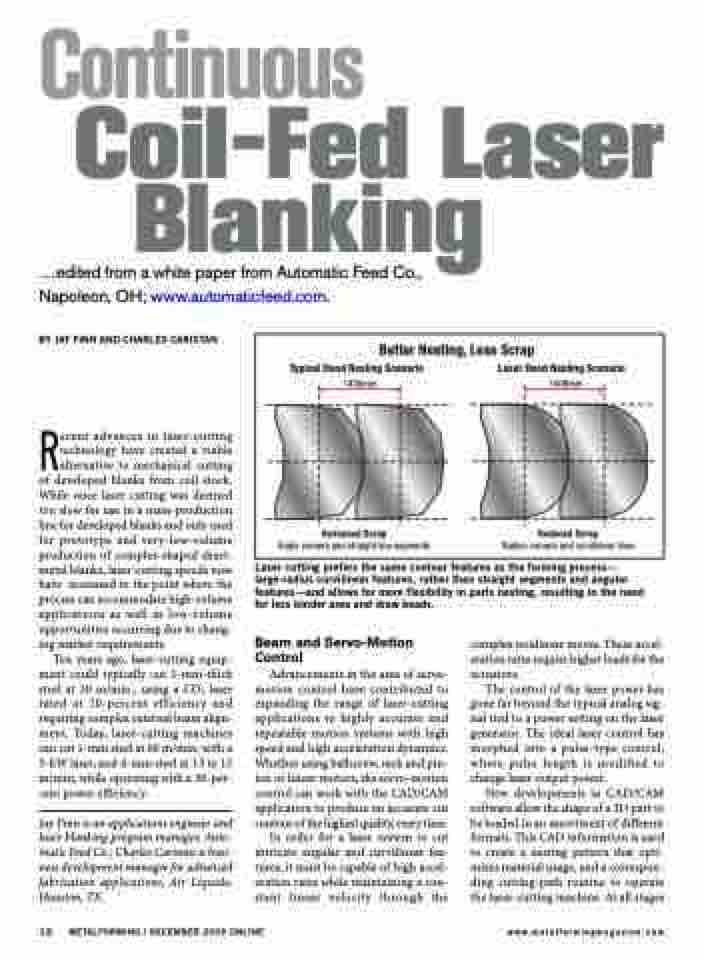
Typical Hood Nesting Scenario
1430mm
Increased Scrap
Angle corners and straight line segments
Laser Hood Nesting Scenario
1406mm
Reduced Scrap
Radius corners and curvilinear lines
Better Nesting, Less Scrap
BY JAY FINN AND CHARLES CARISTAN
Recent advances in laser-cutting technology have created a viable alternative to mechanical cutting of developed blanks from coil stock. While once laser cutting was deemed too slow for use in a mass-production line for developed blanks and only used for prototype and very-low-volume production of complex-shaped sheet- metal blanks, laser-cutting speeds now have increased to the point where the process can accommodate high-volume applications as well as low-volume opportunities occurring due to chang- ing market requirements.
Ten years ago, laser-cutting equip- ment could typically cut 1-mm-thick steel at 30 m/min., using a CO2 laser rated at 10-percent efficiency and requiring complex external beam align- ment. Today, laser-cutting machines can cut 1-mm steel at 60 m/min. with a 5-kW laser, and 4-mm steel at 13 to 15 m/min, while operating with a 30-per- cent power efficiency.
Jay Finn is an applications engineer and laser blanking program manager, Auto- matic Feed Co.; Charles Caristan is busi- ness development manager for advanced fabrication applications, Air Liquide, Houston, TX.
Laser cutting prefers the same contour features as the forming process— large-radius curvilinear features, rather than straight segments and angular features—and allows for more flexibility in parts nesting, resulting in the need for less binder area and draw beads.
Beam and Servo-Motion Control
Advancements in the area of servo- motion control have contributed to expanding the range of laser-cutting applications to highly accurate and repeatable motion systems with high speed and high acceleration dynamics. Whether using ballscrew, rack and pin- ion or linear motors, the servo-motion control can work with the CAD/CAM application to produce an accurate cut contour of the highest quality, every time.
In order for a laser system to cut intricate angular and curvilinear fea- tures, it must be capable of high accel- eration rates while maintaining a con- stant linear velocity through the
complex nonlinear moves. These accel- eration rates require higher loads for the actuators.
The control of the laser power has gone far beyond the typical analog sig- nal tied to a power setting on the laser generator. The ideal laser control has morphed into a pulse-type control, where pulse length is modified to change laser output power.
New developments in CAD/CAM software allow the shape of a 2D part to be loaded in an assortment of different formats. This CAD information is used to create a nesting pattern that opti- mizes material usage, and a correspon- ding cutting-path routine to operate the laser-cutting machine. At all stages
12 METALFORMING / DECEMBER 2009 ONLINE
www.metalformingmagazine.com
