
Page 38 - MetalForming July/August 2009
P. 38
Tooling Technology TOOLING BY DESIGN
PETER ULINTZ
Peter Ulintz has worked in the sheetmetal-forming industry since 1978. His background includes tool and die making, tool and process engineering, engineering management and product devel- opment. Peter also operates the website ToolingbyDesign.com, a source for the transfer of modern metalforming and tool-and-die technology, and which promotes the use of “Performance-Based Die Engineering Strategies.”
Peter speaks at PMA seminars and roundtables focusing on tool and die design, die maintenance, deep drawing, stamping simula- tion, tooling for stamping high- strength steels and problem solv- ing in the press shop.
Peter Ulintz pete.ulintz@toolingbydesign.com www.toolingbydesign.com
The term “stripper” applies to the stripping plate, keepers or retainers, and pressure system (springs, gas, rubber, etc.), which all aid in the strip- ping of stock material from around the punch steel.
Most die-design rules of thumb rec- ommend stripper pressure be equivalent to approximately 10 to 30 percent of the cutting force. In general, softer materi- als and tighter die clearances will require higher stripping force. But for every rule of thumb there is some degree of trade-off for the convenience of apply- ing the rule. In the case of stripping forces, the trade off is die wear.
From a technical perspective, fric- tional forces influence the amount of pressure required for stripping. In high- school physics we learned, “Friction is FN.” This was a convenient way to remember that friction (F) was the product of the coefficient of friction () times the normal force (N). The frictional forces associated with strip- ping force relate directly to the rate at which the punch and die-component cutting edges wear. As a result, a primary design objective should be to reduce the value of
• Punch surface finish, which con- tributes to adhesive wear;
• Punch hardness, which often degrades over time due to poor sharp- ening practices; and
• The type of material being punched.
Factors that influence N include:
• Punch-to-die cutting clearance, which increases the normal force as the clearance is reduced;
• The ratio of hole size to stock thickness;
• The spacing between adjacent holes; and
• The cutting edge conditions on the punch.
Stripper construction plays a signif- icant role in die reliability and durabil- ity. Here are some important design guidelines to consider:
1) Avoid stripper bolts that may become loose and also tend to break at the undercut of the threads.
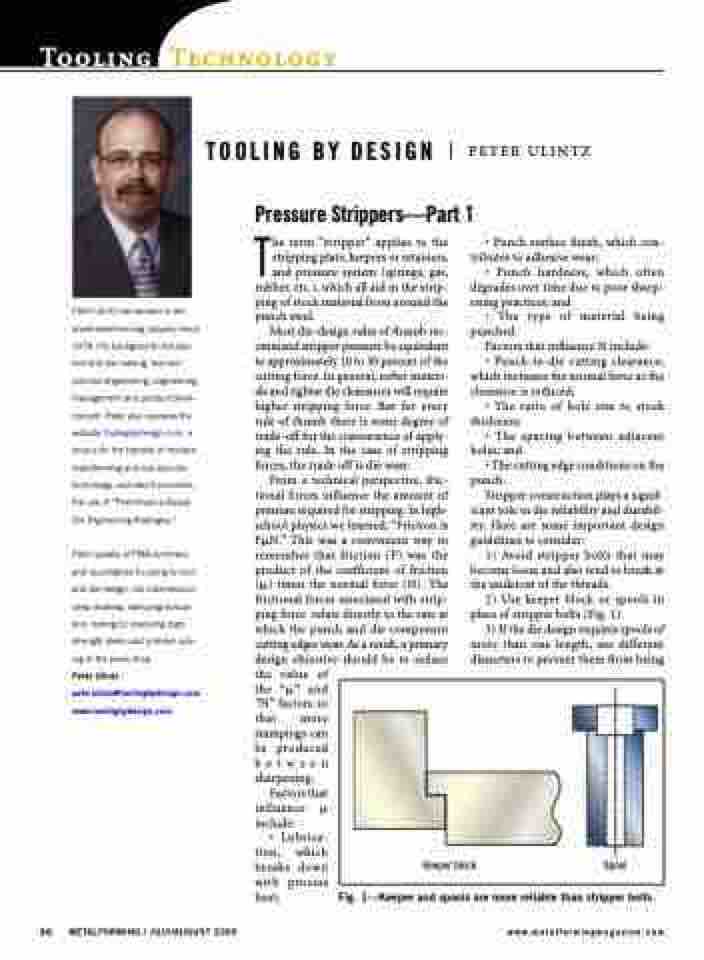
2) Use keeper block or spools in place of stripper bolts (Fig. 1).
3) If the die design requires spools of more than one length, use different diameters to prevent them from being
Pressure Strippers—Part 1
Keeper block Spool
the “” and “N” factors so that more stampings can be produced between sharpening.
Factors that influence include:
• Lubrica- tion, which breaks down with process heat;
Fig. 1—Keeper and spools are more reliable than stripper bolts.
36 METALFORMING / JULY/AUGUST 2009
www.metalformingmagazine.com
