
Page 49 - MetalForming June 2009
P. 49
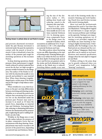
 Venting (shown in yellow) allow air and fluids to escape.
ing the size of the die- entry radius (< 10t), adding draw beads and reducing punch-to-die clearance also may help.
Punch-to-die clear- ances in stretching opera- tions usually are set to one times material thickness (1t). In drawing opera- tions, compressive forces in the flange cause the material to thicken, which
the end of the forming stroke due to excessive thinning and work harden- ing. Punch force and friction increase with stretch-forming depth.
Most tool-and-die professionals understand the need to vent draw dies (see illustration). Venting allows trapped air and lubricants to escape and pre- vents vacuum problems (part sticking) on the upstroke. Venting is very impor- tant for stretching operations, too. If venting is not provided, trapped air and fluids can cause bursting or frac- turing in highly stretched areas. Unfor- tunately, after the breakage occurs, the fluid and air are released and the root- cause “evidence” disappears. Much time and effort can be wasted on tool mod- ifications and material specification changes when the real culprit is trapped air and fluid.
Problem solving in the press shop can be greatly enhanced when you “stretch” your imagination before “drawing” conclusions. MF
pad prevents sheetmetal movement under the pad. Because movement is restricted under the pad, the material in contact with the punch is forced to stretch. It also is beneficial to leave the surface of the pressure pad rough for stretching operations as this increases friction.
In deep-drawing operations, binder pressure (draw-pad pressure) is signif- icantly reduced to permit material flow across the die face, yet high enough to prevent wrinkle formation in the flange area. The surface of the binder in con- tact with the sheetmetal usually is very smooth and polished to ease material flow. When deep drawing irregular- shaped parts, certain areas of the binder may be left rough to help balance mate- rial flow.
When wrinkles do occur, their loca- tions on the part can help differentiate between stretching and drawing modes. Wrinkles on or around the punch nose indicate that restraining forces may be too low on the sheetmetal under the pressure pad. Pressure may need to increase to as much as 10 times the punch force, depending on material type and thickness. Increasing blank size, reducing or eliminating lubrication between the sheetmetal and the pressure pad, roughening the pad or adding lock- beads can also help.
Wrinkles in the flange area or near the die radius indicate the presence of in-plane compressive forces that are synonymous with deep drawing. Draw- pad pressure may need to increase to 40 percent of the punch force, depending on material type and thickness. Reduc-
necessitates an additional 10 to 25 per- cent clearance (1.10t -1.25t), depending on material thickness and type.
The slide position where fracturing occurs can differ depending on the type of forming mode. Drawing failures gen- erally occur within the first one-third of the draw depth. Forming loads (punch force) and friction are greatest early in the stroke and both diminish in mag- nitude as the blank area is reduced. Stretching failures usually occur near
www.metalformingmagazine.com
write no. 37
METALFORMING / JUNE 2009 47
