
Page 18 - MetalForming June 2009
P. 18
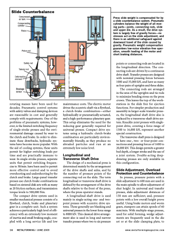
 Slide Counterbalance
Compressed air tank
Compensating cylinder
Piston
Piston rod
Safety rod Tubular rod
Deformation element
Breakage sensor
rotating masses have been used for decades. Pneumatic control systems with safety valves and damping devices are reasonable in cost and generally comply with requirements. One of the problems of pneumatic systems, how- ever, is the limited switching frequency of single-stroke presses and the envi- ronmental damage caused by wear to the clutch and brake. In order to elim- inate these drawbacks, hydraulic sys- tems have become more popular. With the aid of cooling systems, these units permit far higher switching loads per time and are practically immune to wear. In single-stroke presses, separate units that permit switching frequen- cies to 30/min. have been used to permit more effective control and to avoid overshooting and undershooting by the clutch and brake. Large-panel transfer presses use clutch-brake combinations based on sintered disk sets with as many as 20 friction surfaces, and transmission torque levels to 500,000 Nm.
The compact drive system used in smaller mechanical presses consists of a flywheel, clutch, brake and planetary gear in a complete unit. Such a system achieves a particularly high level of effi- ciency with an extremely low moment of inertia and small braking angle, cou- pled with a long service life and low
maintenance costs. The electric motor drives the eccentric shaft via a flywheel, a clutch-brake combination—either hydraulically or pneumatically actuated, and a high-performance planetary gear. This setup eliminates the need for the reducing gear generally required for universal presses. Compact drive sys- tems using a hydraulic clutch-brake combination are particularly environ- mentally friendly, as they produce no abraded particles and run at an extremely low noise level.
Longitudinal and Transverse Shaft Drive
The design of a mechanical press is determined mainly by the arrangement of the drive shafts and axles, and by the number of pressure points of the connecting rod on the slide. The term longitudinal or transverse shaft drive is defined by the arrangement of the drive shafts relative to the front of the press, where the press operator stands.
A longitudinal-shaft drive is used mainly in single-acting one- and two- point presses with eccentric drive sys- tems. These generally are blanking and universal presses in the lower force range to 8000 kN. This classical drive arrange- ment also is used in long and narrow transfer presses where two to six pressure
Press slide weight is compensated for by a slide counterbalance system. Pneumatic cylinders balance the weight of all mov- ing parts—joints, connecting rods, slide and upper die. As a result, the drive sys- tem is largely free of gravity forces—no stresses act on the slide adjustment, and there is an additional safeguard against downward travel of the slide caused by gravity. Pneumatic weight compensation guarantees low-noise vibration-free oper- ation, smooth loading of the motor and short braking distances.
points or connecting rods are located in the longitudinal direction. The con- necting rods are driven by a continuous drive shaft. Transfer presses are designed with nominal pressing forces between 1000 and 35,000 kN, and have as many as four pairs of uprights and three slides.
The connecting rods are arranged in the area of the uprights and tie rods to minimize bending stress on the press crown. This leaves the top of the work- stations in the slide free for ejection functions. For simpler production and assembly in larger-scale transfer press- es, the longitudinal shaft drive also is replaced by a transverse-shaft drive sys- tem. Knuckle-joint presses with single- point drive, covering a force range of 1500 to 16,000 kN, represent another special construction.
The transverse-shaft press is designed to have one-, two- or four-point con- nections and pressing forces of 1600 to 20,000 kN. This design permits a greater bed depth, a longer stroke and the use of a joint system. Double-acting deep- drawing presses are only available in this configuration.
Slide Adjustment, Overload Protection and Counterbalance In presses, pressure points with a slide adjustment to 600 mm are used in the main spindle to allow adjustment of shut height. In universal and transfer presses, slide-adjustment distances of 150 mm are sufficient; and, pressure points with a low overall height prove useful. Using brake motors and worm gears, stampers can attain speeds of 60 mm/min. With multiple-stage presses, used for solid forming, wedge adjust- ments are frequently used in the die set or at the slide clamping plate, to
16 METALFORMING / JUNE 2009
www.metalformingmagazine.com
