
Page 39 - MetalForming April 2009
P. 39
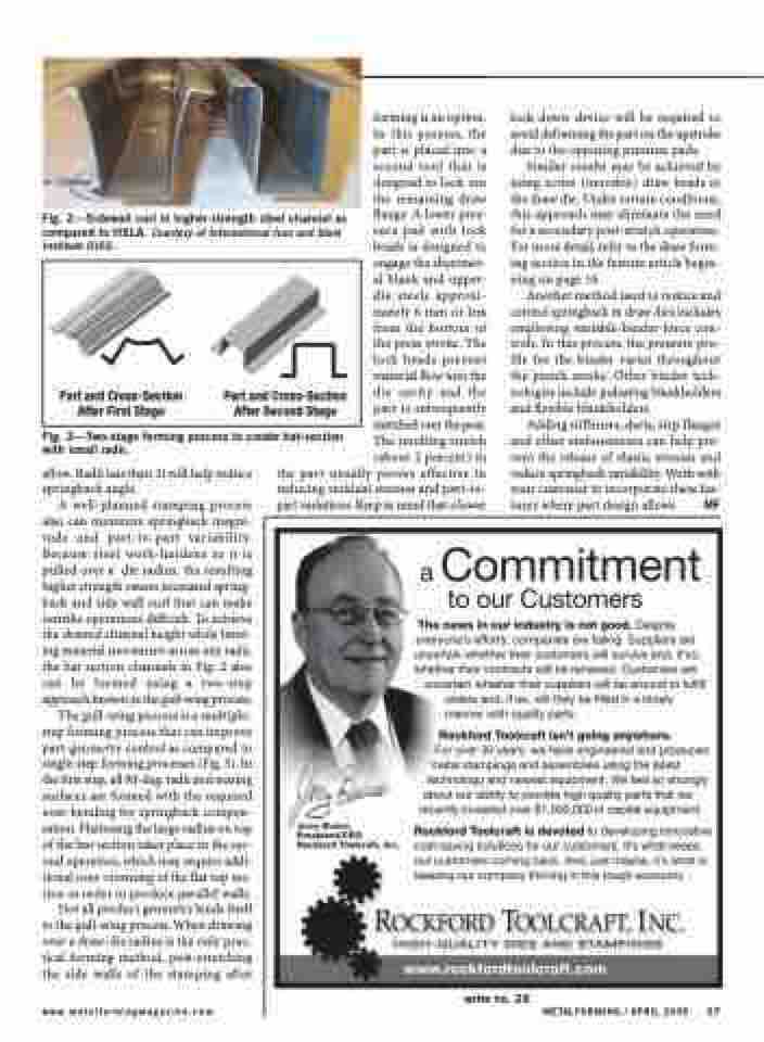
 Fig. 2—Sidewall curl in higher-strength steel channel as compared to HSLA. Courtesy of International Iron and Steel Institute (IISI).
forming is an option. In this process, the part is placed into a second tool that is designed to lock out the remaining draw flange. A lower pres- sure pad with lock beads is designed to engage the sheetmet- al blank and upper- die steels approxi- mately 6 mm or less from the bottom of the press stroke. The lock beads prevent material flow into the die cavity and the part is subsequently stretched over the post. The resulting stretch (about 2 percent) in
lock-down device will be required to avoid deforming the part on the upstroke due to the opposing pressure pads.
Similar results may be achieved by using active (movable) draw beads in the draw die. Under certain conditions, this approach may eliminate the need for a secondary post-stretch operation. For more detail, refer to the draw form- ing section in the feature article begin- ning on page 16.
Another method used to reduce and control springback in draw dies includes employing variable-binder-force con- trols. In this process, the pressure pro- file for the binder varies throughout the punch stroke. Other binder tech- nologies include pulsating blankholders and flexible blankholders.
Adding stiffeners, darts, step flanges and other embossments can help pre- vent the release of elastic stresses and reduce springback variablilty. Work with your customer to incorporate these fea- tures where part design allows. MF
Part and Cross-Section After First Stage
Part and Cross-Section After Second Stage
Fig. 3—Two-stage forming process to create hat-section with small radii.
allow. Radii less than 2t will help reduce springback angle.
A well-planned stamping process also can minimize springback magni- tude and part-to-part variability. Because steel work-hardens as it is pulled over a die radius, the resulting higher strength causes increased spring- back and side wall curl that can make restrike operations difficult. To achieve the desired channel height while limit- ing material movement across any radii, the hat section channels in Fig. 2 also can be formed using a two-step approach known as the gull-wing process.
The gull-wing process is a multiple- step forming process that can improve part-geometry control as compared to single-step forming processes (Fig. 3). In the first step, all 90-deg. radii and mating surfaces are formed with the required over-bending for springback compen- sation. Flattening the large radius on top of the hat section takes place in the sec- ond operation, which may require addi- tional over-crowning of the flat top sec- tion in order to produce parallel walls.
Not all product geometry lends itself to the gull-wing process. When drawing over a draw-die radius is the only prac- tical forming method, post-stretching the side walls of the stamping after
the part usually proves effective in reducing residual stresses and part-to- part variations. Keep in mind that a lower
www.metalformingmagazine.com
METALFORMING / APRIL 2009 37
write no. 26
