Tom Snow Tom Snow
Chairman

Resistance Welding Fasteners to High-Strength Steels

April 1, 2018
0
Comments


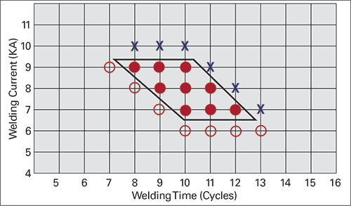
Fig. 1—A proper weld lobe can be developed through an R&D process. The colored dots represent acceptable weld results, clear dots denote the border where weld results rest on the edge of being acceptable and X marks signify positions that fall outside of acceptable results. 
“The resistance-welded nuts on stampings we shipped last week are falling off…please come quick because we’re in danger of shutting down an auto plant!” 

Unfortunately, we get calls like that all too often.

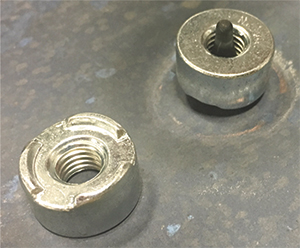
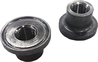
Resistance projection welding of fasteners has been popular for many years, and the wide plastic range of mild steel has made the process possible without much thought. However, welding fasteners to new, lightweight advanced-high-strength steels—which is not as simple and straightforward as it might appear–presents a host of difficulties.

As explained by resistance-welding expert Don DeCorte of RoMan Manufacturing, a maker of resistance-welding transformers, challenges in projection welding nuts and studs to high-strength steels are caused by in-die heattreating processes and base-metallurgy transformations. These result in increased material hardness and inconsistent martensitic surface conditions.


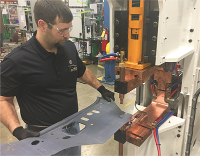
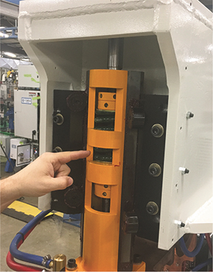
Fig. 2—A threaded nut is welded to a high-strength-steel stamping on a rigid-framed press-type protection welder.

“A wide difference in hardness between high-strength sheetmetal and projections on fasteners makes it difficult to forge the projections into the sheetmetal without severe expulsion and inconsistent weld strength,” says DeCorte. “Resistance-welding problems typically begin when the hardness of sheetmetal exceeds 700 MPA, and some boron and Usibor steels present even more welding challenges, since they can reach hardness levels of 1400 MPA.” 

But, with welding-schedule charts not yet readily available for projection welding fasteners to high-strength steel, a careful R&D process often is needed to identify and optimize the three most important variables in resistance welding: weld force (tip pressure), weld current (secondary amperage) and weld time (duration of current flow).

In our resistance-welding seminars, we teach the concept of determining a proper “weld lobe” during the R&D stage. Numerous articles and even a book have been written on developing these lobes. Simply put, a good weld lobe graphically represents all of the welder settings that will produce customer-specified results (Fig. 1).

Welding-sample tests show that the weld-lobe window of interactive parameters for successfully projection welding nuts and studs to high-strength steels will be much smaller than that for mild steel.


Fig. 3—This standard press-type spot welder features a low-inertia ram equipped with a spring for fast follow-up. The ram's cover has been removed to show the spring. Fig. 4—A "sausage-shaped" projection design on the fastener is recommended for welding to high-strength steel.

A properly sized press-type resistance-welding machine (not a rocker arm), with a rigid frame and a low-inertia ram with fast follow-up, will deliver the best results in applications involving high weld force, high weld current and a short weld time (Fig. 2). This welding schedule creates intense heat at the projections and allows the welding/forging process to take place rapidly—before the projections collapse and blow out. 

In other words, success usually results from setting the machine to weld “hot and fast.” And, whether connected to a pneumatic or servo-actuated ram, the importance of using high weld force and a fast follow-up device, such as a spring built into the ram (Fig. 3), cannot be over-emphasized.

With proper weld-lobe parameters established, start a production run with settings that fall at the center of a graph that documents optimum settings proven through careful testing. Given this, the machine should produce consistently successful results throughout the shift, and if variables begin to drift, some margin is available before the welds fail. However, to avoid shipping a batch of parts that might be rejected, test the welds every hour or so. A push-out-, tensile- or torque-testing device can be used to verify the strength of welded fasteners.

Fig. 5—A weld nut with a ring projection also works well when welding to high-strength steel, especially when a gas- or liquid-tight joint is needed.
Given the proper settings, acceptable weld strength can be obtained from standard AC and MFDC press-type projection welders. However, a growing trend is to use capacitor-discharge (CD) resistance welders, which produce an almost instantaneous, high-amperage burst of power. Our lab tests show that using a CD welder and high force setting can result in welds with approximately twice the strength of other methods, and joints that approach the strength of the base material. Other newer technologies include hybrid CD/MFDC resistance-welding machines and a new “fast-rise” MFDC power-supply design, both of which offer better control of output. 

With a suitable welder identified, the proper fastener geometry will make it much easier to successfully weld nuts and studs to hard, high-strength alloys. According to Ron Foreman, welding-lab manager for Buckeye Fasteners, a supplier of nuts and studs designed for resistance welding, the pointed “upside-down-pyramid” projection designs used for many years in mild-steel applications tend to collapse before a strong joint forms with high-strength alloys. 

To prevent blowout of the projections before they sink into the high-strength sheet, he recommends choosing a fastener with three rounded “sausage-shaped” projections (Fig. 4). Also, when welding fasteners to thick material, Foreman recommends six projections positioned well away from the fastener’s self-piloting ridge. In addition, he reports that rounded 360-deg.-ring projection designs work well (Fig. 5), especially when the joint must be gas- or liquid-tight.

In conclusion, since the requirement to resistance weld nuts and studs to high-strength steel is the new normal, stampers must understand the process and make the necessary changes to avoid expensive rejects. MF

Industry-Related Terms: Alloys, Center, Edge, Projection Welding, Ram, Run, Surface, Weld Nut
View Glossary of Metalforming Terms


See also: T. J. Snow Company

Technologies: Welding and Joining

Comments

Must be logged in to post a comment.
There are no comments posted.

Subscribe to the Newsletter

Start receiving newsletters.